2
AUTO-ON
The AUTO-ON jumper J1, when connected, will cause the indicator to power on automatically
whenever power is applied to the power input connector. If power is lost momentarily and then
reapplied, the indicator will turn on without pressing the ON key. See Figure No. 9 for location.
INTERNATIONAL/
DOMESTIC
JUMPER (J14Intl)
Install the
International/
Domestic jumper,
J14, to comply with
OIML requirements
(see Figure No. 9).
With J14 installed,
the 708 will perform
the following
functions:
1. A “lamp test” will
be performed
on power-up.
2. The printout of
keyboard tare
will be
designated as
“PT.”
Please note the
installation
precautions.
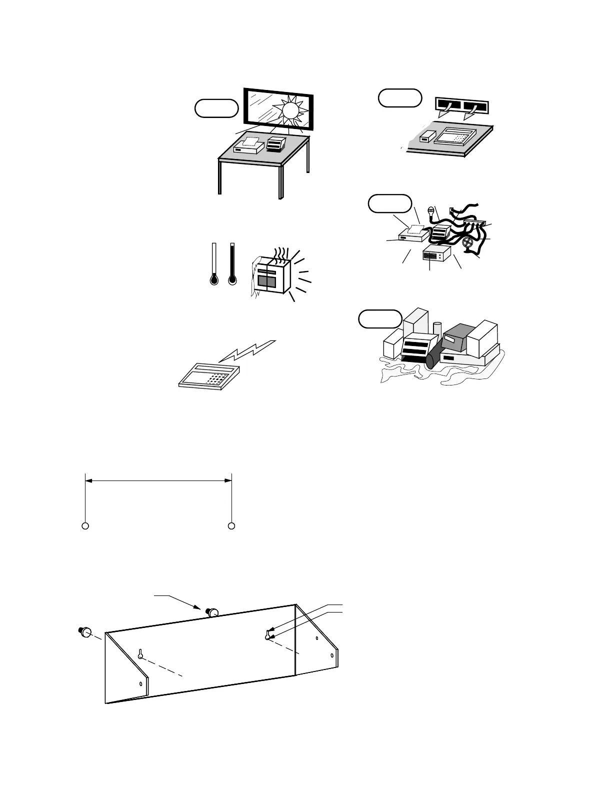
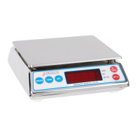
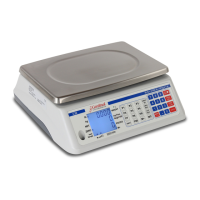
DESKTOP ENCLOSURE
The 708 desktop enclosure may be mounted on a desktop or
other smooth, flat, horizontal surface or it may be mounted
on a wall. Refer to Figure No. 1 for a layout of the wall-
mounting bolts. Regardless of the manner in which the 708
is installed, the location chosen should be free of
temperature extremes and water. It should be in a location
where the display is easily viewed and is not subject to direct
sunlight. The indicator should be mounted such that it is
within easy reach of the operator. If wall mounted, make
certain that the structure and mounting bolts are of sufficient
strength to support the 708.
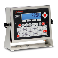
All terminations to the Model
708 Desktop Weight Indicating
Instrument are made at the rear
panel of the instrument.
Connections for the Load Cell
input, the PWC output and the
Serial I/O are all made via “D”
subminiture connectors while
the 12VDC power is connected
using a jack connector. Figure
No. 2 illustrates the layout of the
connector panel.
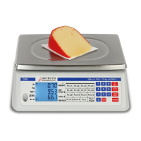
NO!
KEEP THE AREA AROUND THE SCALE
CLEAR
TO PROVIDE ADEQUATE AIR CIRCULATION
PROVIDE ADEQUATE
PROTECTION TO
MINIMIZE LIGHTNING
DAMAGE
NO!
?
PROVIDE GOOD, SAFE GROUND
AND CLEAN AC POWER
DON'T EXPOSE
TO DIRECT SUNLIGHT
NO!
-110˚
32˚-
DON'T EXPOSE TO
TEMPERATURE EXTREMES
NO!
DON'T PLACE IN FRONT OF
HEATING/COOLING VENTS
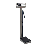
8.000"
clearance for
#10 size screw
.203"
.375"
Figure No. 1