5
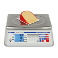
Locate the one for the load cell and
connect the cable as shown. To install a
wire in a terminal block, first press down
on the release bar for the terminal, insert
the wire into the terminal opening then
release the bar locking the wire in place.
Repeat this procedure until all of the
wires and shield have been installed.
NOTE! If the load cell cable does not
contain sense leads, you must install
plug-in jumpers at J2 and J3 to connect
the sense inputs to the excitation leads
on the PC board. If the load cell cable
does contain sense leads, these jumpers
must be removed and stored by placing
them on one pin only.
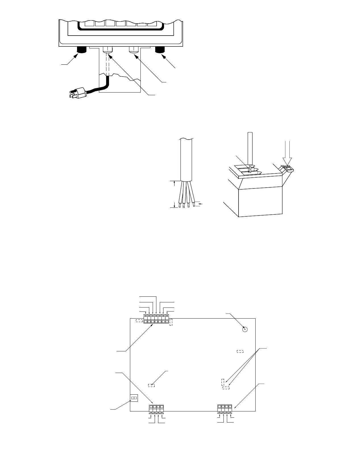
Printer Cable Installation
Loosen the gland connector adjacent to
the power cable gland connector (see
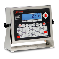
Figure No. 7). Remove 2 inches of the
outer insulating jacket from the cable then
remove 1/4 inch of insulation from each of
the wires (see Figure No. 8). These wires
are to be connected to terminal block P8
at the bottom edge of the printed circuit
board. Refer to Figure No. 9 for the
location of this terminal block.
To terminate the wires, first press down on
the terminal release bar then insert the
wire into the terminal opening and release the bar to lock the wire in place.
Preset Weight Comparator/Checkweigher Logic Level Output
If you so choose, you may use the logic level outputs from your 708 indicator’s preset weight
comparators or checkweigher to control peripheral devices used to manage the flow of material or
signal when the weight is within preset limits. Note that these outputs are at logic level and cannot
drive external devices directly. Solid state relays can be used to accept the logic level output from
the 708 and in turn drive the external device.
Serial
I/O
Load Cell
Power
PWC
Terminal
Insert
Wire
Here
Press
Down
2"
1/4"
-Excitation
-Sense
-Signal
Shield
+Excitation
+Sense
+Signal
J3
J2
P10
PWC/Checkweigher
Output Terminal
Calibration
Switch
12VDC input
Power Jack
Auto
On
J1
-Sens
+Sens
J6
J7
20MA
RS232
RS232
RCD
RS232
TXD
Common
20mA TX
Source
P8
Over/
PWC1
Under/
PWC2
Accept
GND
P4
Serial I/O
Terminals
Serial I/O
Configure
J6 J7
20MA on off
RS232 off on
J14
International
Configuration
Load Cell
Input
Figure No. 9
Figure No. 8
Figure No. 7