3
CAUTION! When in parallel runs, locate Load Cell Cables a minimum of 24 inches
away from all AC wiring.
Load Cell Connection with Over 30 Feet of Cable
For installations with over 30' of
cable between the indicator and the
load cells, sense wires should be
used. The sense wires must be
connected between the +SENS,
-SENS terminals on the indicator
and the +EXCITATION, -EXCITATION wires of the load cells or the +SENS, -SENS terminals of the
load cell trim board or the section seal trim board. For the indicator to utilize the sense wires, the
+SENS jumper J2 and the -SENS jumper J3 must be open (see Figure No. 9).
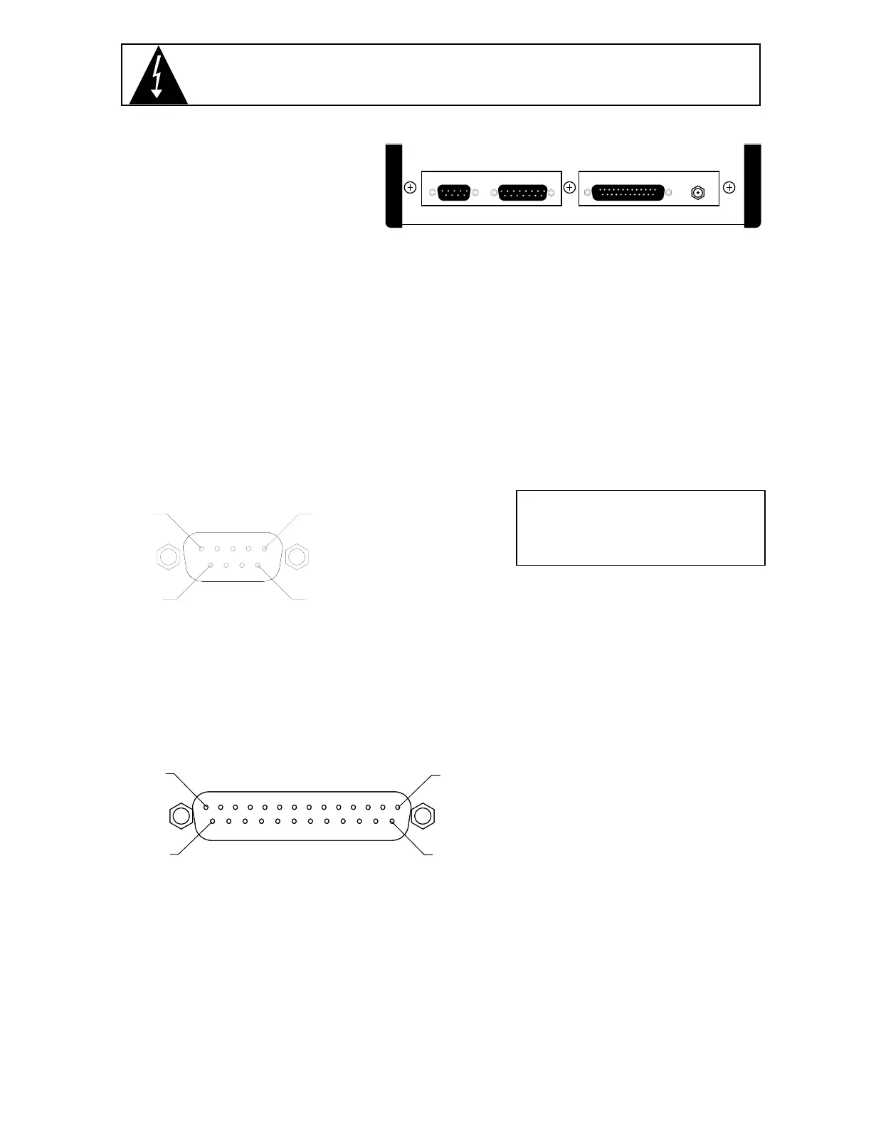
Load Cell Connection
The load cell cable is terminated via a 9-pin connector on the rear panel. Figure No. 3 shows the pin
identification for the load cell connector. Make certain that the pins are correctly identified before
soldering a wire to them. NOTE! If you use sense leads in your load cell installation, jumpers J2 and
J3, located on the printed circuit board, should be disconnected or placed on one pin only. If you do
not use sense leads, jumpers J2 and J3 must be installed to connect the sense leads to the
excitation (refer to Figure No. 9). Make certain that the connector retaining screws are used to hold
the load cell mating connector securely to the rear panel.
Pin No. Function Mating Connector Information
1 +EXCITATION CONNECTOR .................. DE9-P
9 +SENSE CONNECTOR SHELL ...... DE-24657
7 +SIGNAL SCREW LOCK ................. DE-20419
2 -SIGNAL
4 -SENSE
6 -EXCITATION
5 SHIELD
Serial I/O Connection
Your Model 708 may be connected to a printer to record weight and associated data or it may be
connected to a remote display or even to a computer for transmission of weight data. The weight
data may be transmitted on demand (pressing the PRINT key or on receipt of a command from the
computer) or continuously. Figure No. 4 shows the Serial I/O connector along with the identity of the
pins used.
PIN NO. FUNCTION
2 DATA OUTPUT (RS232)
3 DATA INPUT (RS232)
7 DATA COMMON
10 20MA TX SOURCE
11 20MA TX RETURN
Note: Place a jumper on J6 for 20MA interface or on J7 for RS232 interface (see Figure No. 9).
Preset Weight Comparator/Checkweigher Logic Level Outputs
Depending on the mode selected during setup, your Model 708 can function either as a
checkweigher or as a weight indicator with two independent preset weight comparators or with
neither. Regardless of which is selected, the 708 provides logic level outputs that can be used to
control external peripherals. For example, as a checkweigher, these outputs could be used to control
signal lights or buzzers indicating when a weight is within the acceptance range. If the preset weight
comparators are selected, these outputs could be used to control the flow of material onto the scale.
Note, however, that these outputs are at logic level and require a solid state relay to drive the
PIN 5
PIN 1
PIN 9
PIN 6
LOAD CELL
PIN 13
PIN 14
PIN 25
PIN 1
SERIAL I/O
Figure No. 4
Figure No. 3
LOAD CELL PWC OUTPUT SERIAL I/O
12 VDC
0.3A
Figure No. 2