4
external load. When selecting the relays make certain that they are of sufficient capacity to drive the
external load. A setup selection determines whether the device is on or off below the preset value.
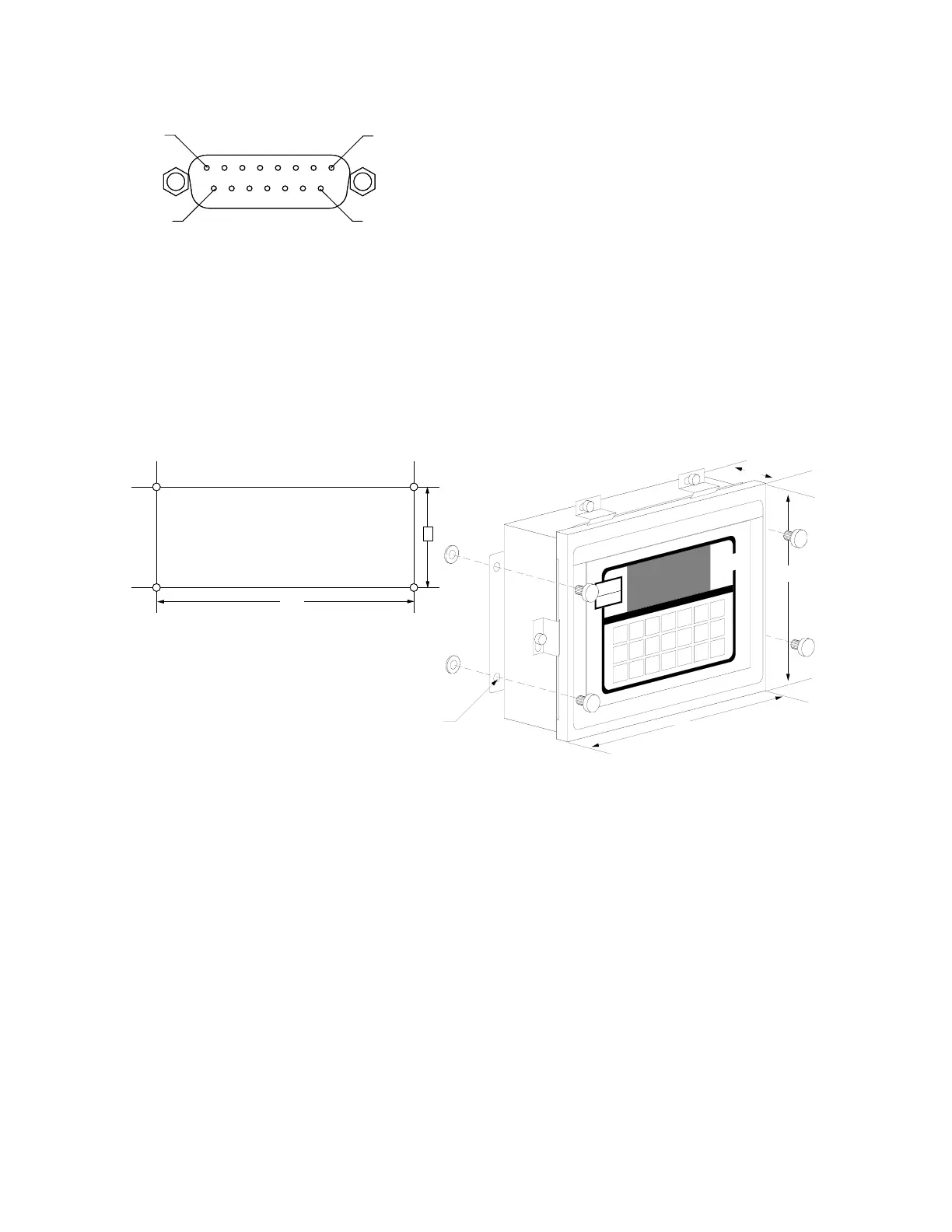
Refer to Figure No. 5 for the layout of the PWC Output connector.
PIN NO. FUNCTION
10 OVER/PWC1
2 UNDER/PWC2
1 ACCEPT
12 GROUND
NEMA 4X ENCLOSURES
For desk mounting of the 708 in the NEMA 4X enclosure, it is necessary to order separately a
“DESK-MOUNT” kit. Refer to Assembly Instruction for Desk-Mount Kit (8539-M097-O1) for mounting
instructions.
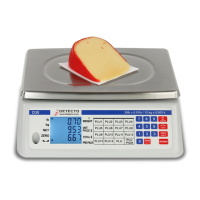
The Model 708 in a NEMA 4X enclosure is normally mounted on the wall or some other vertical
surface. The enclosure is attached to the wall with four (4) bolts. Refer to Figure No. 6 for the hole
layout for the NEMA 4X enclosure.
Make
certain that the location chosen is free
from sudden changes in temperature
and that the mounting surface is strong
enough to support the enclosure while
being close enough to provide the
operator with easy access to the
keyboard. Carefully locate the
mounting hole locations on the wall
then drill and install the anchor bolts. Attached the enclosure to the wall and securely tighten the
retaining bolts.
Continue installation by opening the front cover on the instrument enclosure. Loosen all four (4)
retaining screws and rotate each of the clips to the side. DO NOT REMOVE THESE SCREWS. Fully
open the front cover exposing the internal printed circuit board.
Load Cell Connection
Loosen the cable gland connector for the load cell cable. This gland connector is located on the
bottom of the enclosure on the right-hand side. Refer to Figure No. 7 for an illustration of the
connector layout.
Slip the single cable from the load cell or load cell junction box through the gland connector and into
the enclosure. Remove 2 inches of the outer insulation jacket then remove 1/4 inch of insulation
from each of the wires (either 4 or 6). Refer to Figure No. 8 for an illustration of the proper method of
preparing and then connecting wires to the terminal blocks. Once the cable has been properly
prepared, connect it to terminal block P4 on the main printed circuit board. Figure No. 9 shows the
location of the terminal blocks on the main printed circuit board.
PIN 8
PIN 1
PIN 9
PIN 15
PWC OUTPUT
9.8"
7.3"
3.2"
0.312"
Dia
10.25"
4.0"
Figure No. 6
Figure No. 5