6
To connect the control cable to the preset weight comparator/checkweigher logic level outputs, first
loosen the gland connector located on the bottom of the 708 on the right side. Refer to Figure No. 7
for the exact location of this connector. Slip the cable through this connector and into the enclosure.
Remove 2 inches of the cable insulating jacket then 1/4 inch of insulation from each of the internal
wires. Refer to Figure No. 8. Make the proper terminations on terminal block P10. To terminate a
wire, first press down on the terminal block release bar, insert the wire into the terminal and remove
pressure from the release bar locking the wire in place.
NOTE: After all terminations have been made, remove the excess cable from within the
instrument enclosure and securely tighten each of the cable gland connectors. Do not
over-tighten these connectors but make certain they are snug. DO NOT USE TOOLS
TO TIGHTEN THE CONNECTORS! Tighten only by hand.
Relay Board
The relay board is mounted to the NEMA 4X
enclosure bottom or in an external junction
box for use with the desktop enclosure.
The individual relays can be configured to be
on (closed) or off (open) at weights under the
preset weight and switch at the preset weight
from on-to-off or off-to-on by setting the under
weight condition to on or off during setup and
calibration or setup review.
EXAMPLE: Und1=on. . . PWC1 relay is on
(closed) for weights under the preset weight
and off (open) for weights equal to or over the
preset weight.
NOTE: All relays are the
normally-open type that will
open when power to the
indicator is lost.
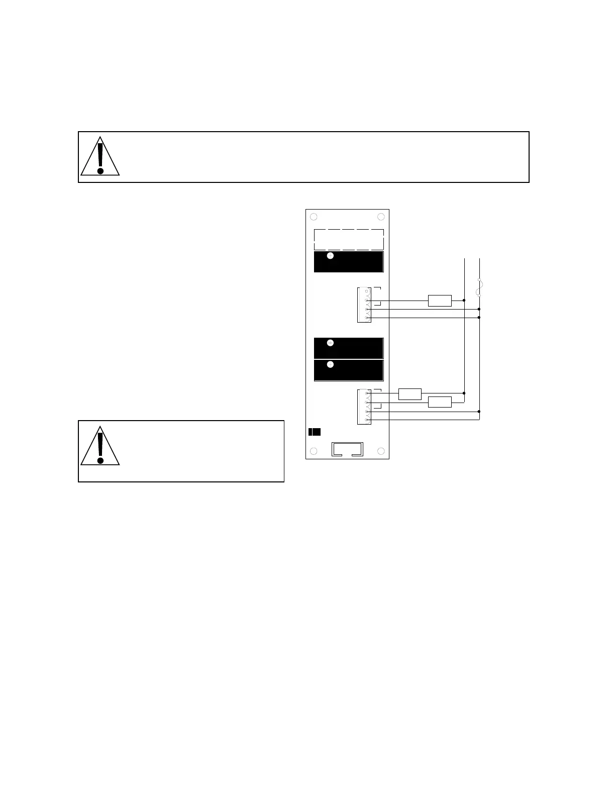
Connect the devices to be controlled as shown in Figure No. 10.
DATA FORMAT SPECIFICATIONS
Serial Data Format
The serial data formats are defined during the setup and review operations. At these times it is
possible to select operation with a computer, remote display (scoreboard) or printer as well as
select the baud rate. Baud rates of 1200, 2400, 4800, 9600 and 19.2K baud are supported. The
data format is fixed at 8 bits with no parity and 1 stop bit.
The serial interface can be configured to operate with a printer (transmits weight data when PRINT
key is pressed), a scoreboard (continuously transmits weight data) or to a computer (transmits data
on receipt of a command from the computer). The actual selection of the mode of operation is made
during the setup and calibration of the instrument. Refer to the applicable section of this manual for
detailed information.
K4K3K2K1
L1 L1 3/7 4/8L1 L1 1/5 2/6
PWC1
PWC2
PWC3
P1
1
PWC
PWC
L2 L1
LOAD
3.0A MAX
LOAD
3.0A MAX
LOAD
3.0A MAX
8539-C062-0K
(28-240 VAC)
Not Used
Accept
L1
L1
Under/PWC2
Over/PWC1
L1
L1
Fuse
3-9 Amp
User Supplied
Figure No. 10