42 4327 • X5 04/2015
• Connect metallic housings or enclosures of installed electrical appliances to the protective conductor system in the craft
(green or green with a yellow stripe conductor).
• Use double-installed or grounded (earthed) electrical appliances.
• If reverse polarity indicator is activated, do not use electrical system. Correct the polarity fault before activating the electrical
system on the craft.
• Test the AC main breakers on a monthly basis by pressing the “T” on the breaker (CE only).
If tripping occurs:
1. Unplug all appliances.
2. Reset the switch.
3. Individually plug in each appliance until the safety switch trips to determine the faulty appliance.
• If the safety switch does not trip with individual appliances, the circuit may be over-loaded.
• If the safety switch trips with no appliances connected, the installation cabling may be damaged. Consult an electrician.
SYSTEM ORGANIZATION
NORTH AMERICA/PACIFIC RIM
OPTIONAL (NA/PR ONLY, NORTHERN AIR CONDITIONING PACKAGE) DUAL 120 VOLT, 30 AMP, 60 HERTZ
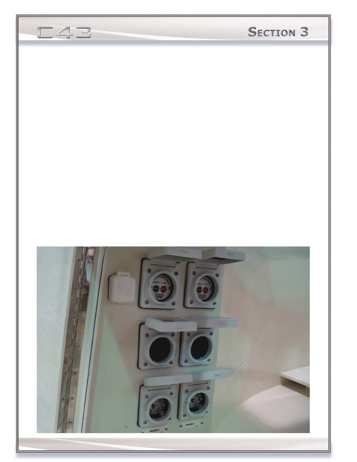
SHORE 1: The SHORE 1 (30 amp) circuit on the AC electrical panel provides power to all the AC equipment except the air
conditioning system. SHORE 1 is congured as 120 volts, 60 Hz. See the breakers on the AC panel for a list of installed
items controlled by the SHORE 1 circuit.
SHORE 2: The SHORE 2 (30 amp) circuit, located on the AC electrical panel, provides power to all the AC components
listed on the SHORE 2 column of circuit breakers on the AC control center. SHORE 2 is congured as 120 volts, 60 Hz. See
the breakers on the AC panel for a list of installed items controlled by the SHORE 2 circuit.
Dual 120 Volt,
30 Amp, 60 Hertz