— 63 —
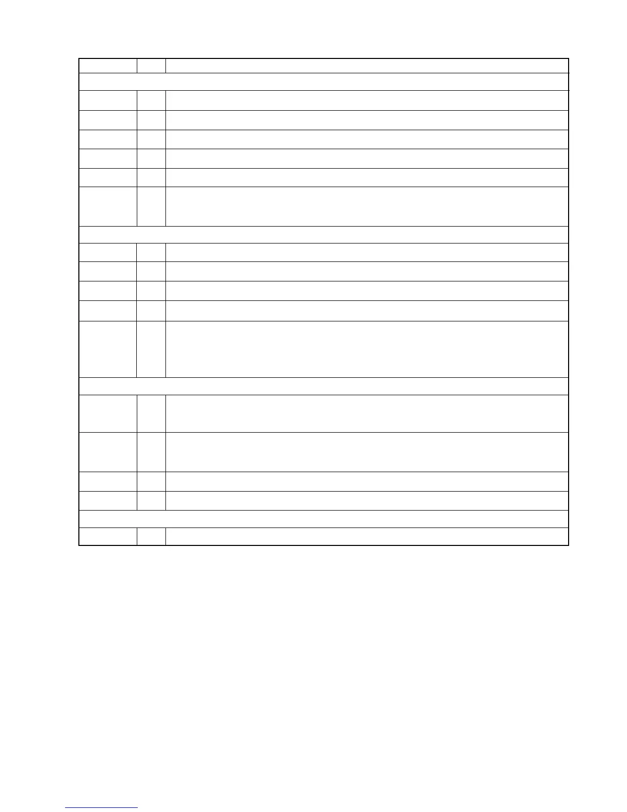
PIN NAME I/O DESCRIPTION
RED
GREEN
BLUE
IREF
CRTVSYN-
CC
CRTH-
O
O
O
I
O
O
Analog Red Current Output
Analog Green Current Output
Analog Blue Current Output
Current Reference Input
CRT Vertical Sync
CRT Horizontal Sync or Composite Sync depending on CCR65 [0]
0 = CRT Horizontal Sync
1 = Composite Sync
CRT Interface
Video Port Interface
P [15:0]
PCLK
VREF
HREF
BLANK/
TVCLK
I/O
I/O
I/O
I/O
I/O
RGB or YUV input/ RGB digital output
Pixel Clock
VSYNC input from PC Card or video decoder
HSYNC input from PC Card or video decoder
Blank output or TVCLK output depending on CCR69 bit 7.
0 = BLANK output
1 = TVCLK output
TVCLK output is used to drive external NTSC/PAL TV encoder. To select NTSC or PAL TV, please refer to
CCR65 register
General Purpose Registers / I2C
USR3
USR2
USR1 / SDA
USR0 / SCL
I/O
I/O
I/O
I/O
General Purpose register. It is recommended to use USR3 to control TV On/Off.
0 = TV display is OFF
1 = TV display is ON
General Purpose register. It is recommended to use USR2 to select NTSC/PAL TV settings.
0 = PALTVCLK
1 = NTSCTVCLK or REFCLK
General Purpose register. USR1/ DDC2/ I2C Data. Can be used to select different test modes.
General Purpose register. USR0/ DDC2/ I2C Clock. Can be used to select different test modes.
Tes t Mode Pi ns
TEST [1:0] I Test mode selects
 Loading...