14
MATERIALS AND DISPOSAL
• These machines are
built with materials that
do not contain sub-
stances that are toxic or
poisonous to the opera-
tor.
• During the disposal phase the
machine should be disassembled and
its components should be separated
according to the type of material they
are made from.
HANDLING AND STOCKING
COMPRESSED GASES
• Always avoid contact
between cables carry-
ing welding current and
compressed gases cyl-
inder and their storage
systems.
• Always close the valves on the com-
pressed gas cylinders when not in
use.
• The valves on Inert gas cylinder
should always be fully opened when in
use.
• The valves on flammable gases
should only be opened full turn so that
quick shut off con be mode in an
emergency.
• Care should be taken when moving
compressed gas cylinders to avoid
damage and accidents which could
result in injury.
• Do not attempt to refill compressed
gas cylinders, always use the correct
pressure reduction regulators and
suitable base fined with the correct
connectors.
• For further information consult the
safety regulation governing the use of
welding gases.
Installation
The installation site for the system must
be carefully chosen in order to ensure its
satisfactory and safe use.
The user is responsible for the installa-
tion and use of the system in accord-
ance with the producer’s instructions
contained in this manual.
Before installing the system the user
must take into consideration the poten-
tial electromagnetic problems in the
work area. In particular, we suggest that
you should avoid installing the system
close to:
• signalling, control and telephone
cables
• radio and television transmitters and
receivers
• computers and control and measure-
ment instruments
• security and protection instruments
Persons fitted with pace-makers, hear-
ing aids and similar equipment must
consult their doctor before going near a
machine in operation. The equipment’s
installation environment must comply to
the protection level of the frame i.e. IP
23 (IEC 60529 publication). This system
is cooled by means of the forced circula-
tion of air, and must therefore be placed
in such a way that the air may be easily
sucked in and expelled through the
apertures made in the frame.
Connection to the
electrical supply
Before connecting the welder to the
electrical supply, check that the
machine’s plate rating corresponds
to the supply voltage and frequency
and that the line switch of the welder
is in the "O" position. Only connect
the welder to power supplies with
grounded neutral.
Use the welder’s own plug to connect it
up to the main power supply. Proceed as
follows if you have to replace the plug:
• 3 conducting wires are needed for
connecting the machine to the supply
• the fourth, which is YELLOW GREEN
in colour is used for making the
"EARTH" connection.
Connect a suitable load of normal-
ised plug (3p+t) to the power cable
and provide for an electrical socket
complete with fuses or an automatic
switch. The earth terminal must be
connected to the earth conducting
wire (YELLOW-GREEN) of the supply.
Table 2 shows the recommended load
values for retardant supply fuses chosen
according to the maximum nominal cur-
rent supplied to the welder and the nom-
inal supply voltage.
NOTE 1:
Any extensions to the power
cable must be of a suitable diameter,
and absolutely not of a smaller diameter
than the special cable supplied with the
machine.
NOTE 2:
It is not advisable to plug up
the welder to motor-driven generators,
as they are known to supply an unstable
voltage.
Usage norms
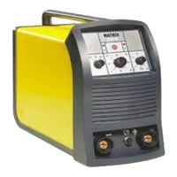
CONTROL APPARATUS (fig. A)
Pos. 1
Supply switch. In the "O" posi-
tion the welder is off
Pos. 2
Welder cable
Pos. 3
Weld gas inlet coupling
Pos. 4
Power connector for cooling
system
Pos. 5
Fast coupling reverse polarity
Pos. 6
TIG weld auxiliary control con-
nector (torch button, remote
control pedal, etc.)
Pos. 7
Fast coupling TIG torch gas
tube
Pos. 8
Fast coupling straight polarity
FRONT PANEL (fig. B)
Pos. 1
“Weld mode” button: 2
STROKE, 4 STROKE, CYCLE,
SPOT-WELD
Pos. 2
“Weld process” button: TIG
with HF arc strike, TIG with
"lift"
type arc strike, ELEC-
TRODE
Pos. 3
Digital display for pre-setting
and visualizing all the parame-
ters. The display also acts as a
digital amperometer
Pos. 4
Digital adjustment/control for
all weld parameters
Pos. 5
PULSATED TIG and EASY
PULSE switch
Pos. 6 SAVE
button to be used for
saving welding programs and
parameters
Pos. 7 PROG
button to be used for
calling welding programs and
parameters up
Pos. 8
POST GAS red led function
Pos. 9
Red led FINAL CURRENT
function
Pos. 10
Red led SLOPE DOWN func-
tion
Pos. 11
Red led PEAK CURRENT (
I
p
)
function - only works with
PULSE function on
Pos. 12
Red led PULSATION FRE-
QUENCY (
f
) function - only
works with PULSE function on
Pos. 13
Red led BASIC CURRENT (
I
b
)
function - only work with
PULSE function on
Pos. 14
RED LED 2
nd
LEVEL CUR-
RENT (
I
2
) function, only works
with CYCLE function on
Pos. 15
GREEN LED MAIN CURRENT
(
l
1
) function
Pos. 16
Red led SLOPE UP function
Table 2
Model MATRIX 250 HF
I
2
Max nominal 35% (*) A 250
Installation power kVA 7
Nominal current "gl" class fuses A 10
Supply connection cable
Length m3
Section
mm
2
1,5
Earth cable
mm
2
35
(*) Service factor

 Loading...