15
Pos. 17
Red led INITIAL CURRENT
function
Pos. 18
Red led PRE-GAS function
Pos. 19
Red led for ARC FORCE func-
tion
Pos. 20 SET
button to be used for
selecting welding parameters
Pos. 21
Red led for HOT START func-
tion
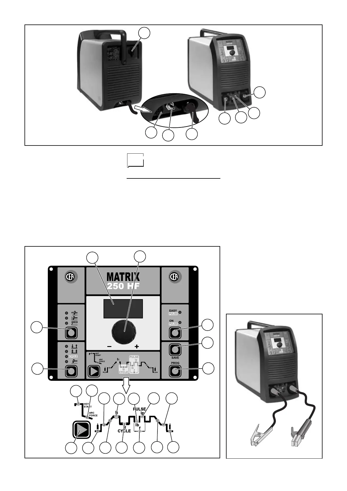
Connection of the
welding cables
ELECTRODE WELDING (MMA)
With the machine disconnected from the
supply, connect the welding cables to
the out terminals (positive and negative)
of the welder, connecting them to the
gripper and the earth, with the correct
polarity provided for the type of elec-
trode to be used (Fig. C).
Choosing the indications supplied by the
electrode manufacturer, the welding
cables must be as short as possible,
close to one other, and positioned at
floor level or close to it.
TIG WELDING
• Connect the gas pipe at the rear of the
machine to the Argon gas cylinder
then open it (pos. 5, fig. D).
• When the machine is switched off
connect the earth cable to the quick
coupling marked + (positive) (pos. 3,
fig. D).
• Connect the relative earth clamp to
the piece to be welded or nearby
ensuring that the area is free from
rust, paint, grease, ecc..
• When the machine is switched off
connect the earth cable to the quick
coupling marked - (negative) (pos. 1,
fig. D).
• Connect the torch gas tube to the con-
nection (pos. 2, fig. D).
1
5
6
7
8
2
3
4
Fig. A
1
2
3
4
5
6
7
8
9
10
11
12
13
20
15
14
17
16
19
18
21
Fig. B
Fig. C