page 19 www.centsys.com
Gate Rack
OPERATOR INSTALLATIONSECTION 7
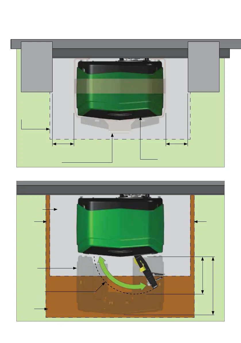
7.1.2. Minimum Clearances
Below are site plan examples illustrating the minimum clearances required when
installing the D10 SMART, D10 Turbo SMART or D20 SMART.
FIGURE 9. MINIMUM CLEARANCES - SIDES
FIGURE 10. MINIMUM CLEARANCES - FRONT
120mm
175mm
Pillar
Foundation
Trench
Trench
Gearbox
Trim
Trench
Most
extreme
path of
the Override
Lever
Gate Rack
Pillar
Theft-deterrent Cage
D10 SMART / D10 Turbo SMART
/ D20 SMART
Foundation
20mm (Minimum)
40mm and above(Ideal)
20mm (Minimum)
40mm and above(Ideal)