page 24 www.centsys.com
7.1.4. Foundation Plate Installation
7.1.4.1. New Concrete Foundation
OPERATOR INSTALLATIONSECTION 7
The Foundation Plate can either be set into a new concrete foundation, as in
Section 7.1.4.1, or bolted down onto an existing concrete plinth as in Section
7.1.4.2.
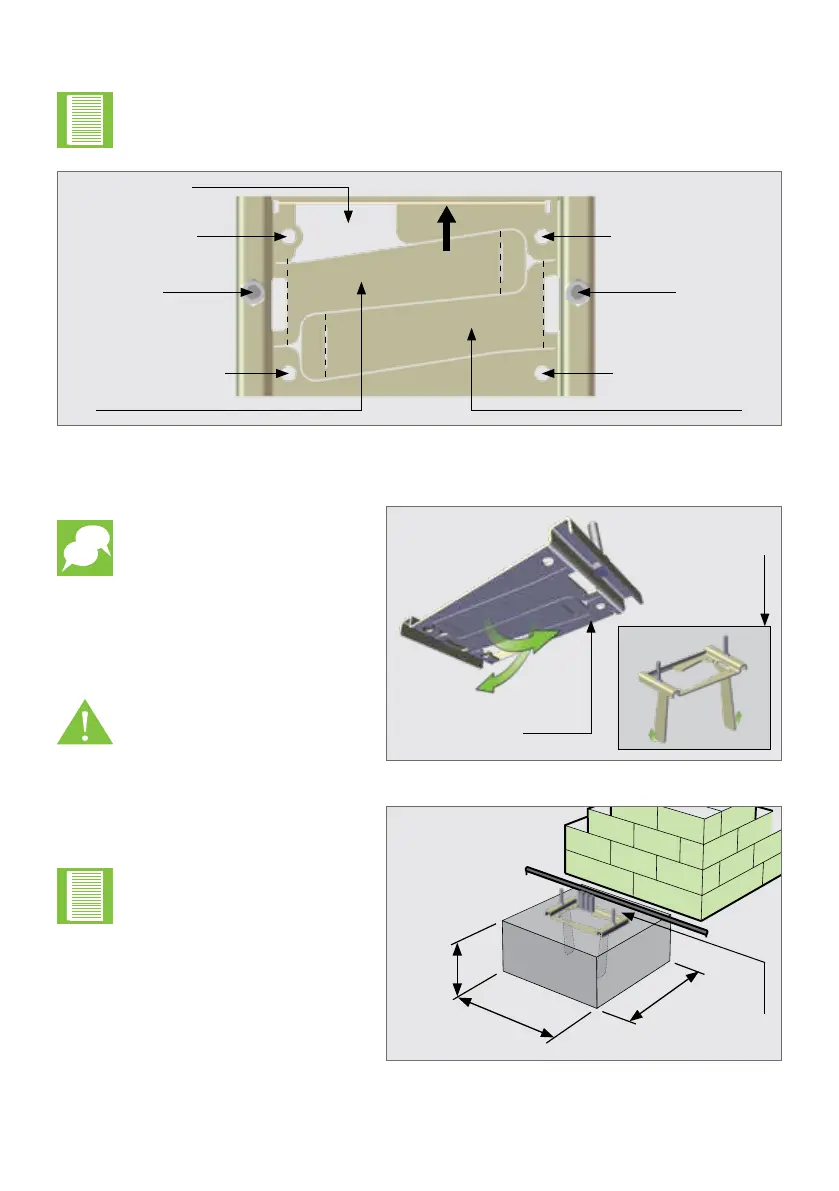
FIGURE 17. FOUNDATION PLATE ASSEMBLY - TOP VIEW
FIGURE 18
Bottom face of the
Foundation Plate
View once tabs
have been bent
down correctly
Mounting Bolt
Tab
Cutout for Conduit
(New and Existing
Installations)
Towards Gate
Tab
Bolt-down point for
existing Concrete Plinth
Bolt-down point for
existing Concrete Plinth
Bolt-down point for
existing Concrete Plinth
Bolt-down point for
existing Concrete Plinth
Mounting Bolt
Using a pair of pliers, gently bend
the two tabs of the Foundation Plate
down to a 90° angle as shown in
Figure 16.
Be careful not to deform
the Foundation Plate
while bending the tabs.
Check that the M10 half-
nuts are tightened to 20Nm
on the mounting bolts.
FIGURE 19
Cabling conduit exiting at the
back of the Foundation Plate
Using medium-strength concrete
(25MPa), cast the plinth according to
the dimensions as shown in Figure 19.
Lay the cabling conduit so
that it routes the cables to
the back of the Foundation
Plate. Ensure that 30mm
of conduit protrudes above
the concrete.
300mm
300mm
400mm