page 35 www.centsys.com
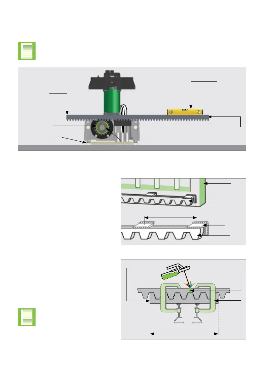
Pinion Spyder
First
Secured End
Spirit Level
Pinion
Foundation
Plate
FIGURE 46. THE RACK AND OPERATOR FROM THE GATE'S PERSPECTIVE
Slide the gate halfway along the rst section and level the unsecured end, ensuring that
the rack is resting on the Pinion Spyder, not pressing down. Continue this way to x all
sections.
Level this end of the rack,
and x it to the gate
Before fully xing each section of rack, slide the gate backwards and forwards
along the section, checking that the rack is only resting on the Pinion Spyder,
and not pressing down onto it.
OPERATOR INSTALLATIONSECTION 7
7.9.1. Fitting Steel Rack to the Gate
FIGURE 47
FIGURE 48
±300mm
Gate
Steel
Rack
Welded
join
Clamp
O-cut
Steel
Bracket
Steel
Rack
Fix the Steel Rack with the steel
angle brackets
1
. The brackets must
be spaced no more than 300mm
apart.
When joining dierent lengths of
Steel Rack, a simple way of ensuring
that the correct pitch spacing is
achieved, is to clamp a small o-cut
between the two pieces.
Do not weld the o-cut
to the gate or the join.
±300mm
1. The Steel Angle Brackets are not supplied with the D10 SMART / D10 Turbo SMART / D20 SMART.