page 20 www.centsys.com
OPERATOR INSTALLATIONSECTION 7
D10 SMART - Steel Rack
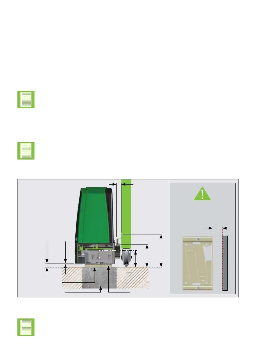
FIGURE 11. STEEL RACK ABOVE PINION
1. Includes 3mm clearance required between rack and pinion
2. Distance between bottom of the Foundation Plate and bottom edge of the Rack Tooth
If there is space to mount the rack underneath without fouling the ground as the
gate moves, the following are the pros and cons:
Pros
• The rack is more hidden from view
• It provides a very eective anti-lift bracket
• It ensures that, since the gate beds in, the rack does not drop onto the
pinion, loading the operator unnecessarily
Cons
• Rack teeth face up vertically, potentially collecting dirt
• Could require the use of a custom bracket
To ensure that the operator does not protrude into the driveway, install the base plate at
least ush with the driveway entrance.
It is typical to mount the rack above the pinion as shown in Figures 11, 13 and 15.
However, Figures 12, 14 and 16 shows the rack mounted underneath.
7.1.3. Locating the Operator's Position
The measurements given below are based on the rack supplied by
Centurion Systems (Pty) Ltd and are to be used as guidelines only.
5mm
25mm
91mm
121mm
1,2
176mm
1
25mm
(Typical Steel
Rack Width)
Flat bar welded
to Foundation Plate
and rail
Concrete Foundation
(Recommended to allow
for adjustment)
Minimum space from edge
of Foundation Plate to
reference point of edge that
protrudes the furthest.
(Section 7.1.1.)
Foundation Plate
50mm
The principles of installation on a Steel Rack is to position it in the middle of the
output pinion with the operator fully forward on the slots.