page 23 www.centsys.com
OPERATOR INSTALLATIONSECTION 7
D20 SMART - Steel Rack
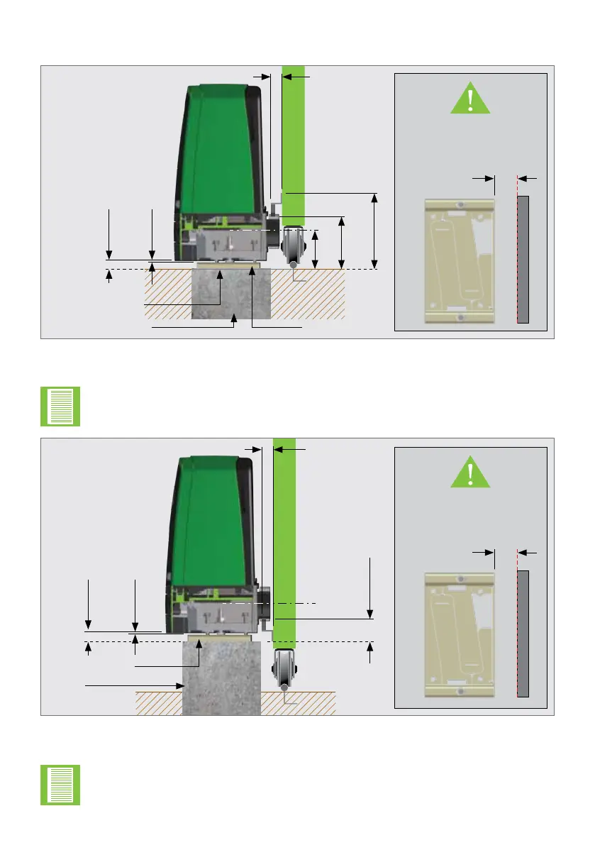
FIGURE 15. STEEL RACK ABOVE PINION - D20 SMART
1. Includes 3mm clearance required between rack and pinion
2. Distance between bottom of the Foundation Plate and bottom edge of the Rack Tooth
5mm
25mm
91mm
113mm
1,2
168mm
1
25mm
(Typical Steel
Rack Width)
Flat bar welded
to Foundation Plate
and rail
Concrete Foundation
(Recommended to allow
for adjustment)
Minimum space from edge
of Foundation Plate to
reference point of edge that
protrudes the furthest.
(Section 7.1.1.)
Foundation Plate
50mm
The principles of installation on a Steel Rack is to position it in the middle of the
output pinion with the operator fully forward on the slots.
FIGURE 16. STEEL RACK BELOW PINION - D20 SMART
1. Includes 3mm clearance required between rack and pinion
2. Distance between bottom of the Foundation Plate and top edge of the Rack Tooth
5mm
25mm
25mm
(Typical Steel
Rack Width)
59mm
1,2
Foundation Plate
Raised
Concrete
Foundation
(Recommended to allow
for adjustment)
The principles of installation on a Steel Rack is to position it in the middle of the
output pinion with the operator fully forward on the slots.
Minimum space from edge
of Foundation Plate to
reference point of edge that
protrudes the furthest.
(Section 7.1.1.)
50mm