48
Troubleshooting (continued)
Symptom Possible Causes Diagnosis Resolution
LCD wall control
is o or not
functioning
(display shows
nothing or is unlit,
and wall control is
unresponsive)
(end)
Faulty wiring Perform this test only after verifying
main board WALL CTRL terminals.
Verify wall control wiring:
Disconnect wires from wall control
and measure the DC voltage on
the wiring at the end near the wall
control.
If voltage is not between 11 and 13
volts DC, wiring is faulty.
If voltage is absent or out of range,
turn o power to operator and
disconnect batteries if present. Wait
30 seconds and then reconnect
batteries and reapply AC power.
If fault persists, replace or repair
wall control wiring.
Faulty wall control Perform this test only after verifying
wall control wiring.
Check voltage at wall control:
With a voltmeter, test for 12VDC at
the screw terminals on the rear of
the wall control. If 12V is present and
wall control is not active, wall control
is faulty.
If 12V is absent only when the wall
control is connected, wall control
may have internal short circuit.
Replace faulty wall control.
Main board DC
IN fuses blow
immediately upon
powerup
Stray wiring/metal
contacting main
board
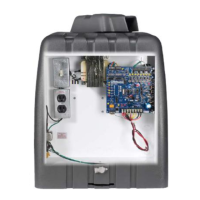
Visually inspect E-box. Check for
any metallic objects or bare wires
that may be inadvertently touching
the main board.
Prevent metallic objects or bare
wires from touching the main board.
Turn power o and replace fuses,
then re-apply power.
Internal short on
main board
Turn o AC power. Disconnect all
wiring from main board except DC
IN power wiring. Replace fuses and
reapply power. If fuses still blow
immediately, fault is in main board.
replace main board
Door moves in
wrong direction
when pressing up/
down buttons
Reverse mounting
mode congured
wrong (reverse
limits)
Check the setting for the reverse
mounting mode (reverse limits)
ensure the setting is correct
Wiring for
open and close
terminals swapped
(does not apply to
LCD wall control)
Check that open button is
connected to OPEN terminal and
close button is connected to CLOSE
terminal.
Correct wiring.
(ONLY applies to
units with Battery
Backup)
Unit reports that it
is on battery power
even when AC
power is present
AC power path
issues
Disconnect batteries, check if
powerhead main board powers o.
If powerhead main board loses
power, leave batteries disconnected
and follow troubleshooting for
'Powerhead main board is o'
AC input voltage
mis-selected
(120V/240V
models only)
Check whether the transformer
connector is plugged in to the
connectors on the EMI lter board
marked '120V' or '240V.'
Verify this matches the input AC
voltage supplied to the operator.
Note that if incorrect voltage is
applied to the operator, damage to
the operator electronics may have
occurred.
Ensure voltage selection is correct
and verify operator functionality.
AC power out of
range
Verify input AC voltage:
Measure AC voltage between 'L1'
and 'L2' terminals at EMI lter board
input connector. Verify voltage is
within specications.
If voltage is outside specications,
see resolution.
Ensure the circuit supplying the
operator is the correct voltage class
for the operator (e.g. 120V, 240V,
or 480V)
If voltage is out of specication for
the circuit, consult an electrician.