EasyManuals Logo

Chenbro RM238 Series User Manual

Chenbro RM238 Series
71 pages
To Next Page IconTo Next Page
To Previous Page IconTo Previous Page
Page #62 background imageLoading...
Page #62 background image
RM238 Series
Backplane │ 62
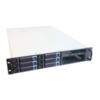
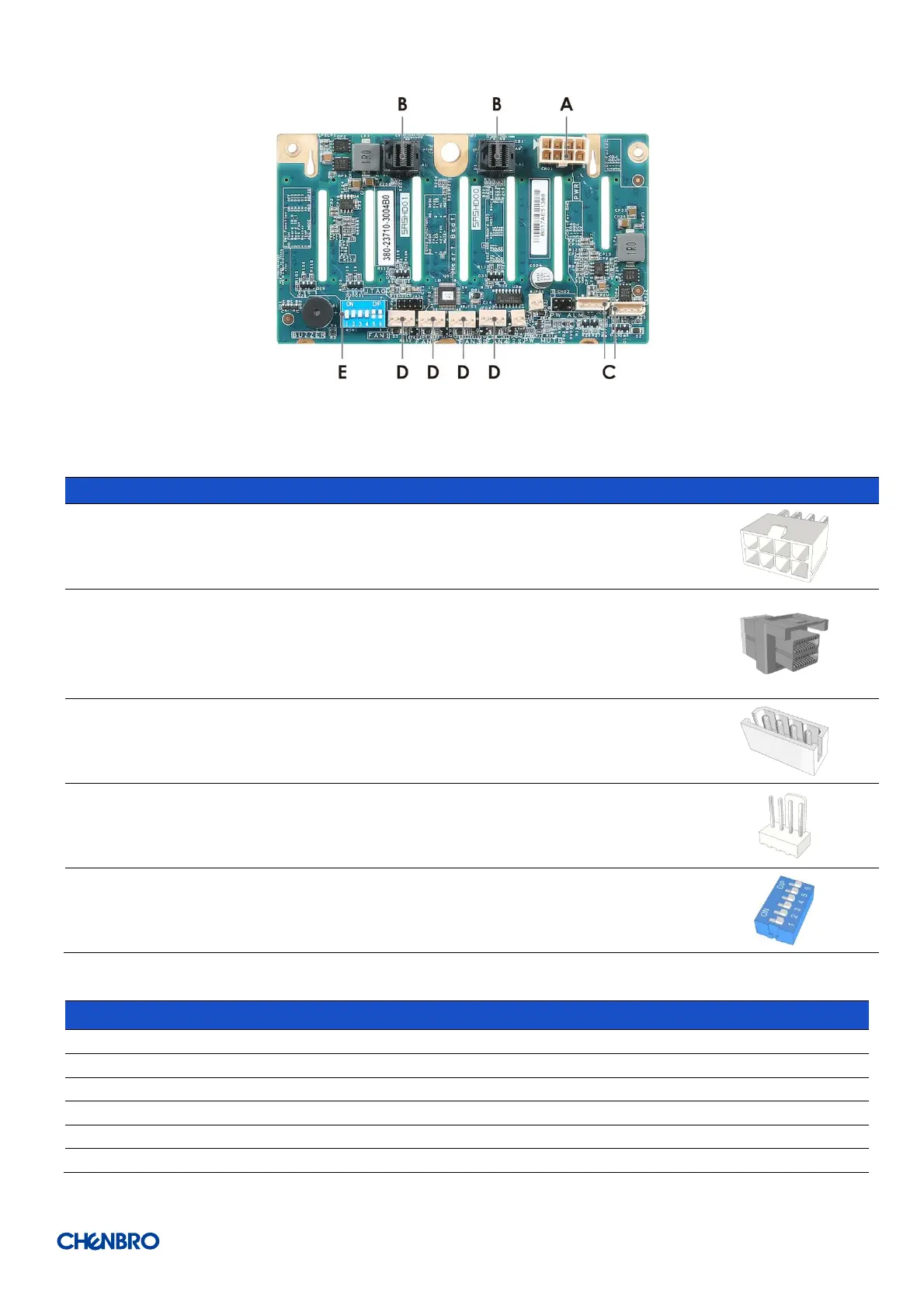
Figure 81 Backplane rear view
Table 24 Connector and pin header function description
Label
Connector
Description
Drawing
A
Power
The backplane includes one power connector
supplying 12V input to the backplane. Power is
routed to the backplane via a power cable harness
from the power supply.
B
Mini-SAS HD
The backplane includes two multi-port Mini-SAS HD
connectors providing data signals for eight
SATA/SAS drives on the backplane. A cable can be
routed from matching connectors on the server
board or add-in SATA/SAS HBA cards.
C
I2C
The backplane includes two 4-pin connectors. One is
used as a management interface to the server board
and the other is for BP to BP communication.
D
Fan
The backplane includes four fan connectors used to
control and monitor fan speed.
E
DIP Switch
Follow below the DIP switch setting table.
Table 25 Dip switch setting
PIN-Number
PIN-Definition
ON
OFF
1
Board ID 0
EN
DISABLE
2
Board ID 1
EN
DISABLE
3
System Fan
EN
DISABLE
4
Buzzer Alarm
EN
DISABLE
5
Temperature Alarm
55
65
6
ACC Mode
HDD
SGPIO

Table of Contents

Questions and Answers:

Question and Answer IconNeed help?

Do you have a question about the Chenbro RM238 Series and is the answer not in the manual?

Chenbro RM238 Series Specifications

General IconGeneral
BrandChenbro
ModelRM238 Series
CategoryChassis
LanguageEnglish

Related product manuals