Edge/Edge Blanket Repair
7-33
Roll Photosensors Alignment
The roll photosensors watch as the corners
of the flatwork move between the clutch-brake
rollers and turn off when only a small portion of
material remains pinched between them.
If these sensors are out of alignment, a wrong
amount of corner will be left for the transfer
clamps to grab the flatwork. This can result in
dropped flatwork or in poor lay down.
Required Tools
7/16”, 1/4” wrenches, thin slotted
screwdriver
Perform only when the unit is OFF
with power connected.
Use extreme caution.
Turn power OFF at the main disconnect
switch.
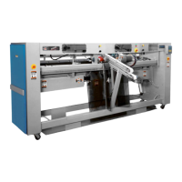
To work on the right roller, remove the
inlet motor cover (Figure 7-44, A) and
then the inlet mechanism cover (B). To
work on the left roller, remove just the
inlet mechanism cover (C).
NOTE: Physical constraints
require that first the motor cover
be loosened, then the inlet
mechanism cover removed, and
finally the motor cover removed.
1.
2.
Turn power ON at the main disconnect
switch.
Press the green START button.
Press any of the red safety STOP but
-
tons.
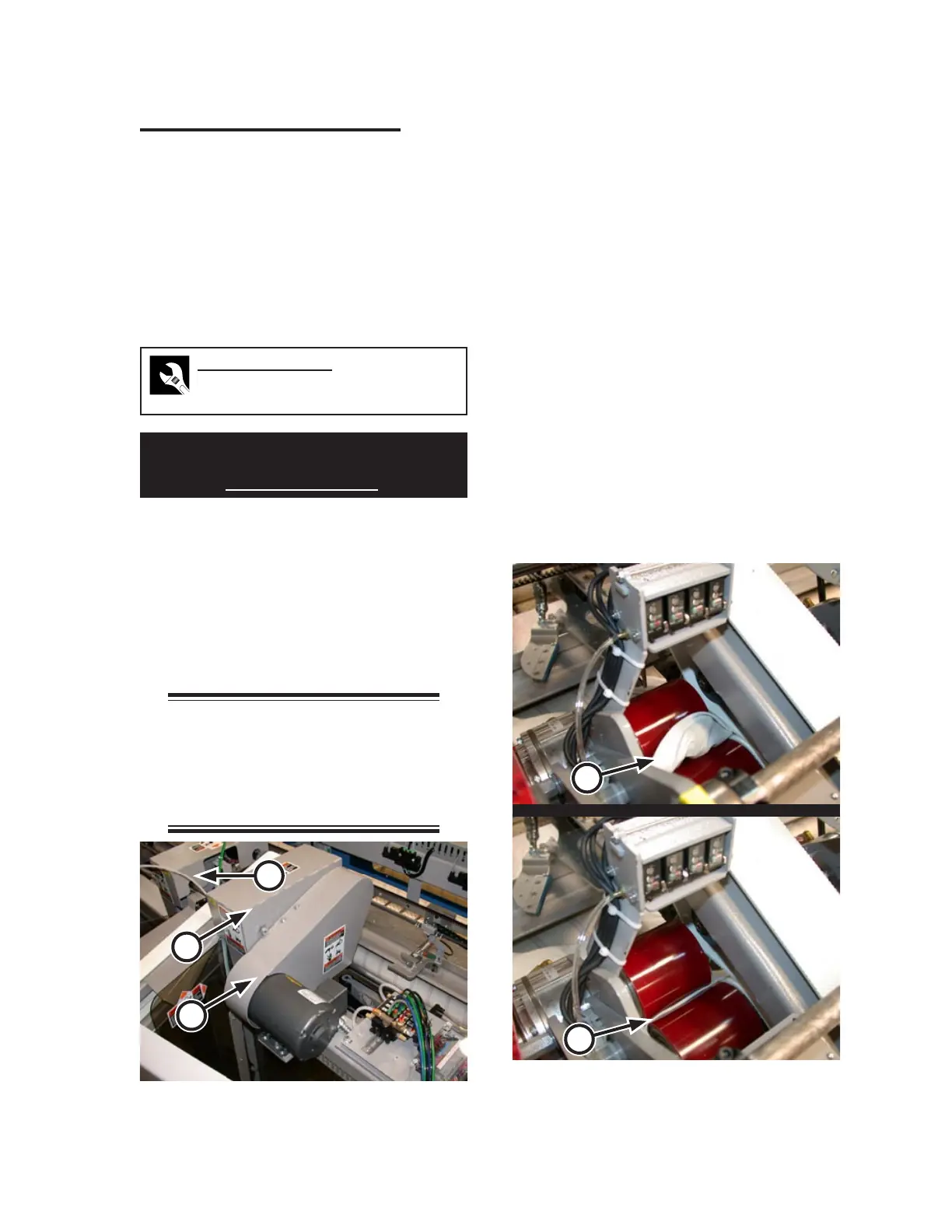
Working on one set of sensors at a time,
work a small piece of flatwork between the
clutch-brake rollers so that a few inches
of material is visible (Figure 7-45, A).
Both red and green LEDs on the sensors
should be lit.
By hand, turn the clutch-brake rollers;
keeping an eye on the photosensor LEDs
as you do so.
When only about 1/8” of material is show
-
ing evenly, the red LEDs should extinguish
while the green remain lit (Figure 7-45,
B).
3.
4.
5.
6.
7.
8.
Figure 7-45: With only about 1/8” showing, the red
LEDs should go out while the green
remain lit.
A
B
Figure 7-44: Safety covers must be removed to gain
access to the transfer clamp rollers.
A
B
C