Installation Edge/Edge Blanket
2-18
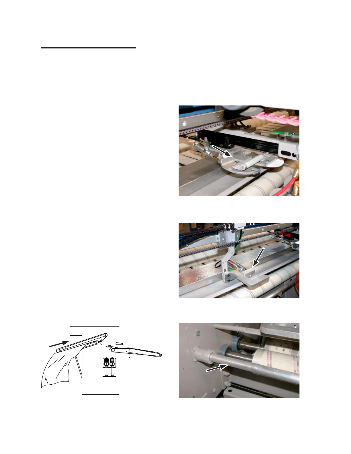
Spread/Feed Function Check
Use a sheet or similar piece of flatwork to
test the feeder. Press a STATION button to
select a program. Stand clear of all moving
parts and watch for the following:
The piece is carried upward by the
input conveyor (Figure 2-31) to the
transfer point.
The transfer clamp, located at the cen
-
ter of the unit (Figure 2-32), moves for-
ward and grabs the flatwork as close as
1-1½” from the corners, where it is held
for the spreader clamps to grab it.
The spreader clamps (Figure 2-33) and
lower spreader belts spread and smooth
the flatwork.
The laydown air blast occurs (Figure
2-34) and the piece is smoothed by the
doffer rolls as it travels on the discharge
ribbons.
Turn power OFF at the main disconnect
switch. The Start/Stop button lamp and the
CHI panel display will go out.
Each photosensor on the unit is physically
aligned and sensitivity adjusted for testing
purposes before shipment.
1.
•
•
•
•
2.
3.
Figure 2-33: Spreader belts smooth the flatwork
stretched with the spreader clamps.
Figure 2-34: An air blast pushes the flatwork onto
the discharge conveyor ribbons.
Figure 2-32: The transfer clamp grabs the corners
of the flatwork. Note: The blanket unit
does not have the white nylon roller.
Figure 2-31: The piece is carried upward by the
input conveyor.
Different environments require alignment
and sensitivity adjustments during instal
-
lation to ensure reliable operation of the
sensors. Sensors that are misaligned or out
of adjustment can miss a piece of flatwork
or give a false signal when no material is
there. For more information, refer to the
REPAIR chapter,
Sensors
section.
4.