Operating Principles Edge/Edge Blanket
5-14
5.3 Mechanical System
Components that make up the mechanical
system include the following:
Inlet Drive System
Spread Drive System
Discharge Drive System
•
•
•
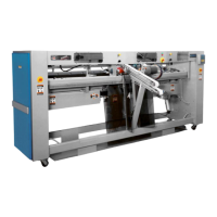
Figure 5-13: Side view of the inlet drive system.
Inlet Drive System
Use the illustration (Figure 5-13) and picture
(Figure 5-14) below to identify the mechanical
components of the inlet drive system. Note that
both stations have identical inlet sections.
The inlet motor (Figure 5-13, A) powers
he inlet drive system. A shaft from this motor
extends directly into a drive pulley (B).
This pulley drives a belt (C) which powers
both the lower (D) and upper (Figure 5-14/15,
E) inlet belt drive pulleys. An idler pulley (F) is
included in the drive chain so that pulleys D and
E turn in opposite directions.
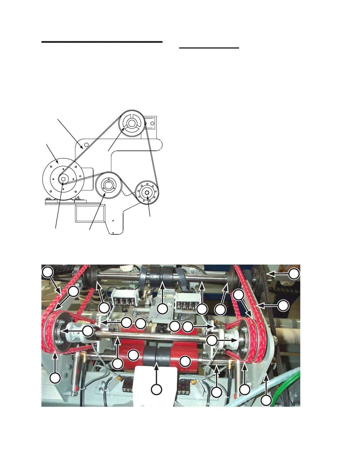
A shaft (Figure 5-16, G) extends through
pulley D. Attached to this shaft is a drive roll
(H), which powers the lower inlet belt, and two
idler rolls (1, 2) which will be discussed later in
this section.
A shaft (I) also extends through pulley F.
Attached to this shaft is a drive roll (J), which
powers the upper inlet belt. Also attached are
two pulleys (K, L) which transmit power to the
first set of twist belts (M, N). These belts together
power another set of pulleys (O, P) mounted on
shaft (Q).
Figure 5-14: Additional components indirectly driven by the inlet motor.
G
H
D
E
I
J
K
L
M
N
R
S
U
T
V
W
Q
P
O
2
1
4
3