Operating Guidelines Edge/Edge Blanket
3-4
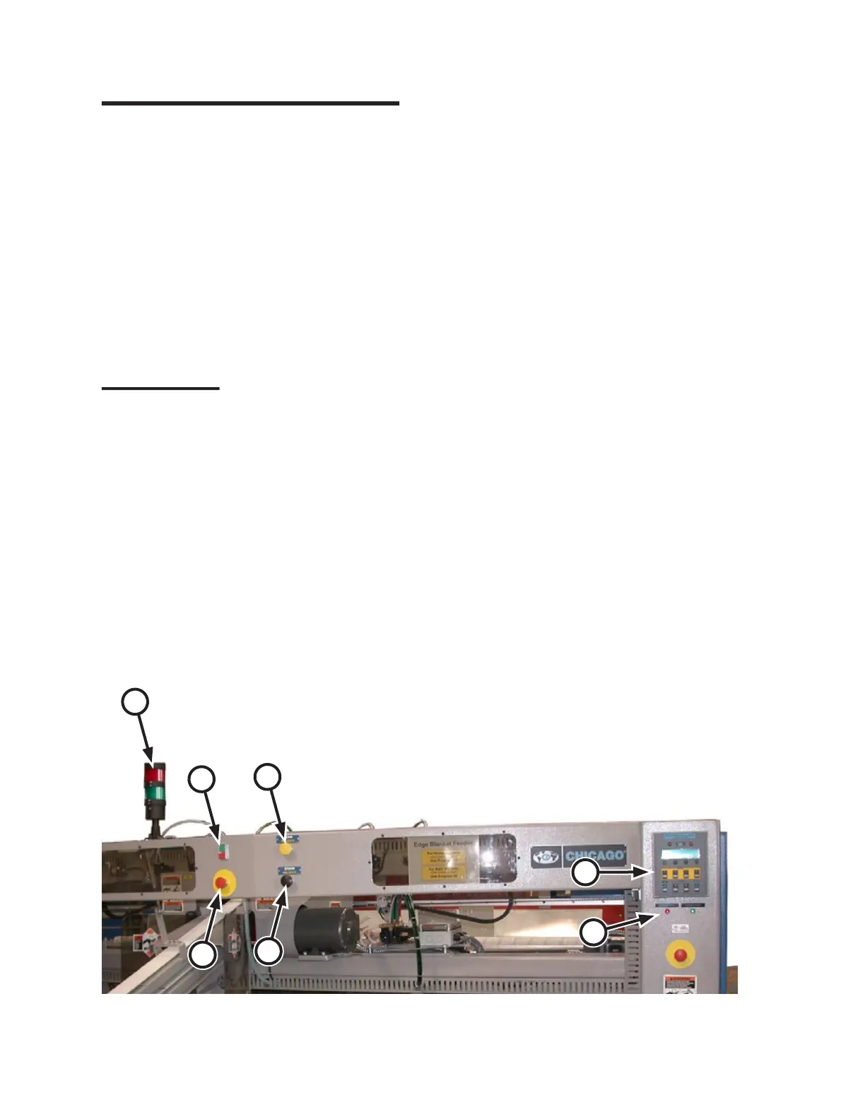
Figure 3-8: Controls located at the front of the feeder unit.
A
C
B
D
G
E
F
3.2 Operating Controls
All operating controls are externally mounted
on the machine and most are clearly marked with
nameplates.
References to these functions are capitalized
in this manual for easy identification. Detailed
descriptions are given in the following
paragraphs.
Most of these controls are located at the front of
the machine. There are duplicate sets of operator
controls as well as non-duplicated controls.
Front Controls
Controls at the front of the unit include (Figure
3-7):
START/STOP buttons (A)
Safety STOP buttons (B)
STAIN REJECT (option) button (C)
TEAR REJECT (option) button (D)
CHI Panel (E)
INTERCONNECTED STOP CIRCUIT
(option) indicator lights (F)
Pacing Lights (option) (G)
•
•
•
•
•
•
•
START/STOP button (A):
Initiate and pause general machine operation.
Each station has a set. The green
Start button
starts all moving parts while the red
Stop button
pauses operation of the unit.
During normal operation, the integrated lamp
glows steadily when the unit is running. The lamp
flashes when either a red station Stop button or a
red safety STOP button is pressed.
Safety STOP button (B):
Provided to help assure operator safety and
to prevent damage to the unit. There are six
of these red safety STOP buttons, one at each
operator station and one on each endframe, front
and rear.
When pressed, these stop all moving parts,
release internal air pressure, and lock out
operation of the unit.
A red safety STOP button stays pressed down
until manually reset by twisting clockwise.
Before restarting the unit, correct the problem
that resulted in the red safety STOP button being
pressed.
STAIN/TEAR REJECT buttons (option)
(C, D):
Determine how stained or torn flatwork are
handled by the CHICAGO
®
folder at the end of
the line. If equipped, each operator station has a
set of these buttons.
 Loading...