General Information
1-5
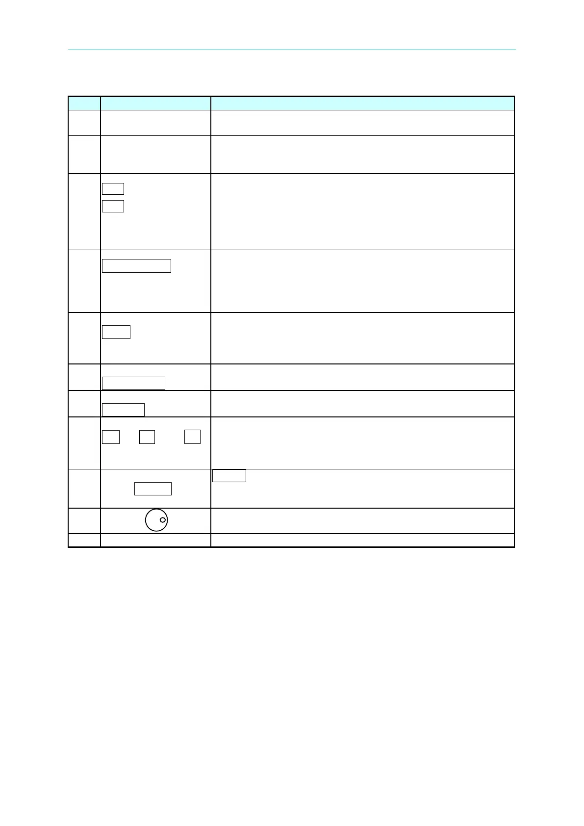
Display: The LCD displays the configuration, output setup, and
measurement results.
Indicator LED: “OUT” and “SHIFT”, for showing activation of
output and shift mode, are available and
located on the keypad
area next to the corresponding keys.
---------or--------
PAGE
Cursor moving keys: These two keys move the cursor to
different directions respectively. In normal mode, pressing
any of these two keys will change the place of the cursor.
Under shift mode, these keys enable the LCD display to
change to the last page or next page if or patterns
appear
in the lower right of display.
PAGE/EXIT
---------or---------
SAVE
PAGE or EXIT command key: Pressing this key will switch the
LCD display between MAIN PAGE and CHOICE PAGE, or
change to CHOICE PAGE in each functional list. Under shift
mode, pressing this key in CHOICE PAGE, it can save the
/ -
----------or---------
Backspace and Minus command key: Pressing this key will
erase the keyin number. It may show “-“ if there is
Under shift mode, pressing the key in CHOICE PAGE, it can
recall system data (see 3.8).
OUT/QUIT command key: Pressing this key may enable the
AC Source output voltage or quit the output voltage.
Shift mode selection key: Pressing this key will switch the AC
Source from normal operational mode to shift mode.
0 to 9 , and
------------or-----------
Numeric and decimal keys: The digital and decimal keys can
program the numeric data.
ENTER
ENTER key: It is to confirm the setting of parameters.
RPG: The programming data and options can be inputted by
turning the RPG to the desired ones.
Main power switch: It powers on or off the AC Source.
Table 1-1 The Description of the Front Panel