Digital Power Meter 66200 Series User’s Manual
MODEL NO.
SERIAL NO.
CAT II
ALL INPUT
500Vrms
500Vrms
500Vrms
20Arms
V+ V-
I+ I-
! !
!
!
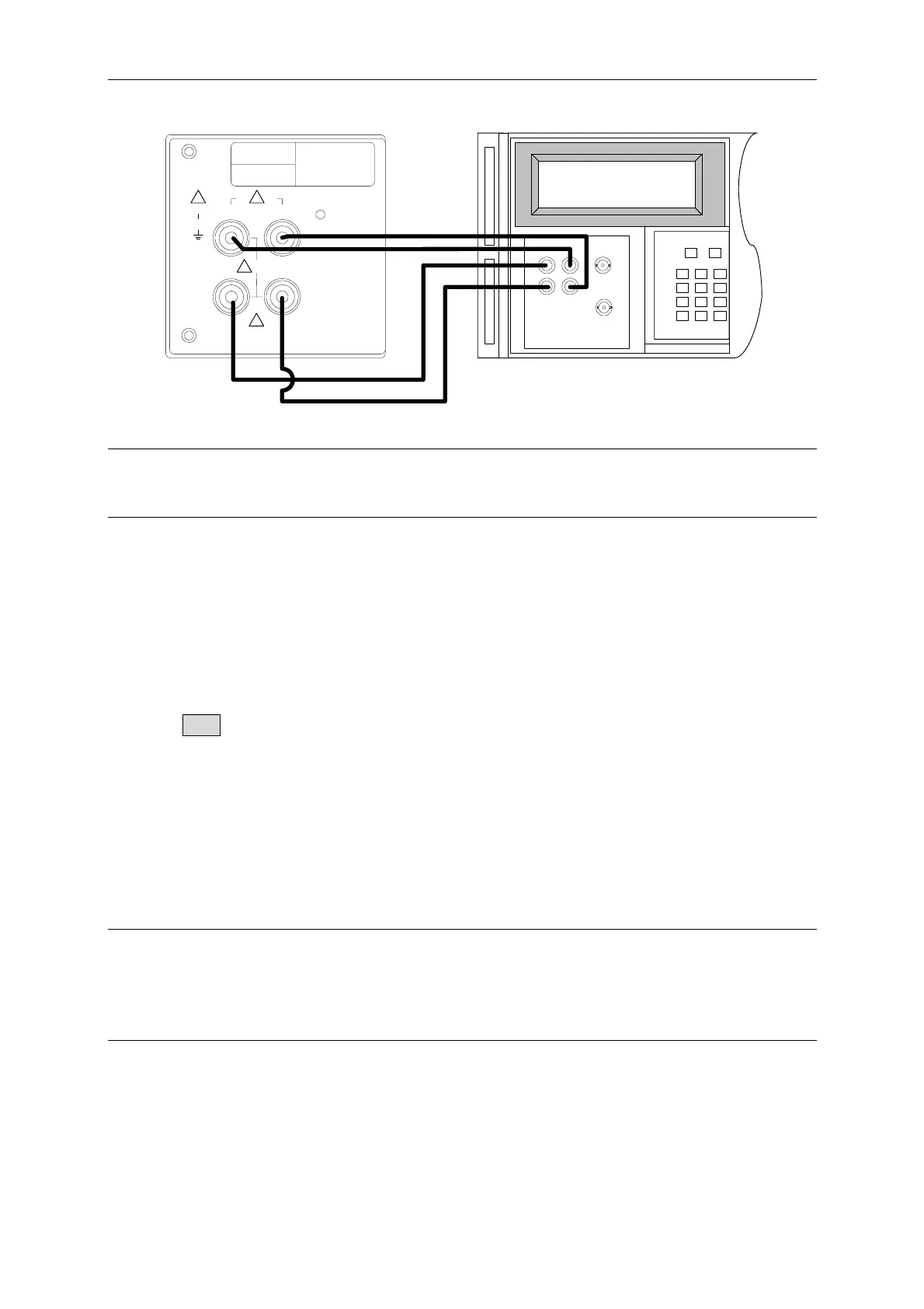
Figure E-1
a CAUTION
Be sure the voltage and current wire position are connected correctly. It could burn out the
instrument internal circuit if mistake.
Voltage Measurement Specification Verification
Steps:
1. Set the voltage range of 66200 Series Power Meter to 500Vrms, the voltage measurement
display is set to V (AC voltage RMS).
2. Follow the test table to set the high voltage output of Fluke 5500A.
3. Press OPR to set the Fluke 5500A to begin output.
4. Log the voltage RMS showed on the 66200 Series Power Meter voltage measurement
display panel.
5. Follow the test table to set the low voltage output of Fluke 5500A.
6. Repeat step 3 and 4 to log the 66200 Series Power Meter panel readings.
7. Set the Fluke 5500A output to Standby and follow the test table to switch the 66200 Series
Power Meter voltage range.
8. Repeat step 2 to 7 and measure the voltage of remaining ranges.
9. Once the test is completed, set the Fluke 5500A output to Standby.
aCAUTION
Make sure the Fluke 5500A output is OFF when switching the voltage range to avoid any
measurement error. Do not touch the test wire when performing Fluke 5500A output test to
prevent electric shock. Once the test is done, make sure the Fluke 5500A output is OFF
before changing the wire configuration to avoid electric shock.
E-2
 Loading...


