Panel Description
(12) Function Setting
Indicator
:
It shows the setting mode when in Setup or shows PASS/FAIL
when executing GO/NG. When the RMT LED is on, it indicates
the system is under remote control.
(Note 5)
Note:
1. 66201 Digital Power Meter is applicable for small current range measurement only, so there is no
Current Shunt indicator.
2. 66201 Digital Power Meter is applicable for small current range measurement only, so there is no
high current range indicator.
3. 66201 Digital Power Meter provides the measurements of I (current RMS), Ipk+ (positive peak
current) and Ipk- (negative peak current) only.
4. 66201 Digital Power Meter provides the parameters of PF (Power Factor), CFi (Crest Factor of
Current) and F (Frequency).
5. 66201 Digital Power Meter has Limit and Meas function for setting.
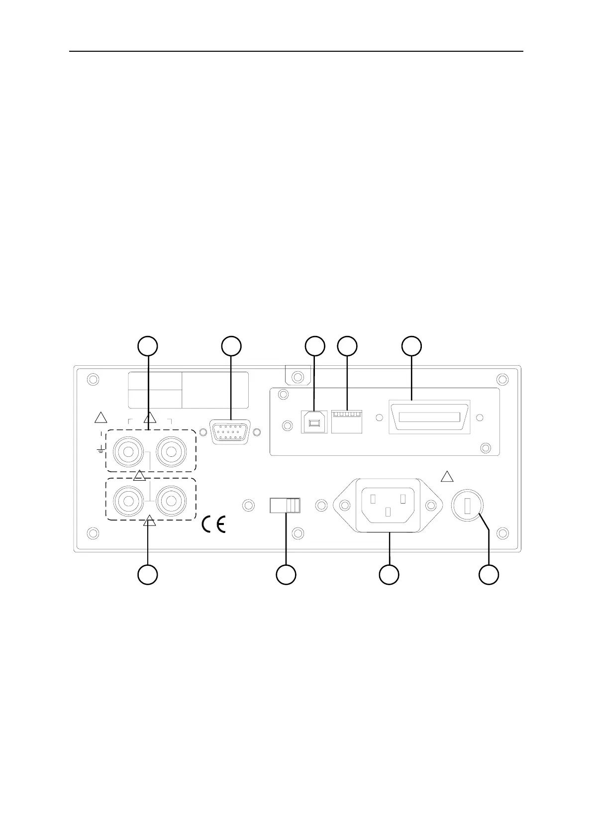
3.2 Rear Panel
MODEL NO.
SERIAL NO.
CAT II
ALL INPUT
500Vrms
500Vrms
500Vrms
20Arms
V+ V-
I+ I-
CONTROL
SIGNALS
VOLTAGE RANGE
~90 to 130V / 180 to 250V
50Hz / 60Hz 30VA Max
AC LINE
FUSE
T500mA/250V
GPIB
USB
! !
!
!
!
1234
5 6 7 8 9
Figure 3-2 Rear Panel of 66200 Series Digital Power Meter
The following explains the parts on the rear panel of 66200 Series Digital Power Meter and
their operation details.
(1) Fuse Holder :
It is the fuse holder for power supply.
(2) AC LINE Inlet :
It is the power supply connection socket that is connected
by power cord.
(3) VOLTAGE Range Switch :
AC input voltage selector that can switch to 110V or
220V.
(4) Voltage Measurement
Input Terminal
:
It is the positive/negative terminal input for voltage test
point.
3-3
 Loading...


