Appendix A Using Control Signal Input/Output Terminal
Appendix A Using Control Signal
Input/Output Terminal
The rear panel of 66200 Series has a 15-pin D_type terminal for external trigger signal and
external Pass/Fail display. The table below lists the pin definition:
Pin Definition Pin Definition Pin Definition
1 +5V 6 GND 11 Fail -
2 N/A 7 N/A 12 Fail +
3 N/A 8 Limit Trigger 13 N/A
4 GND 9 GND 14 Pass -
5 N/A 10 N/A 15 Pass +
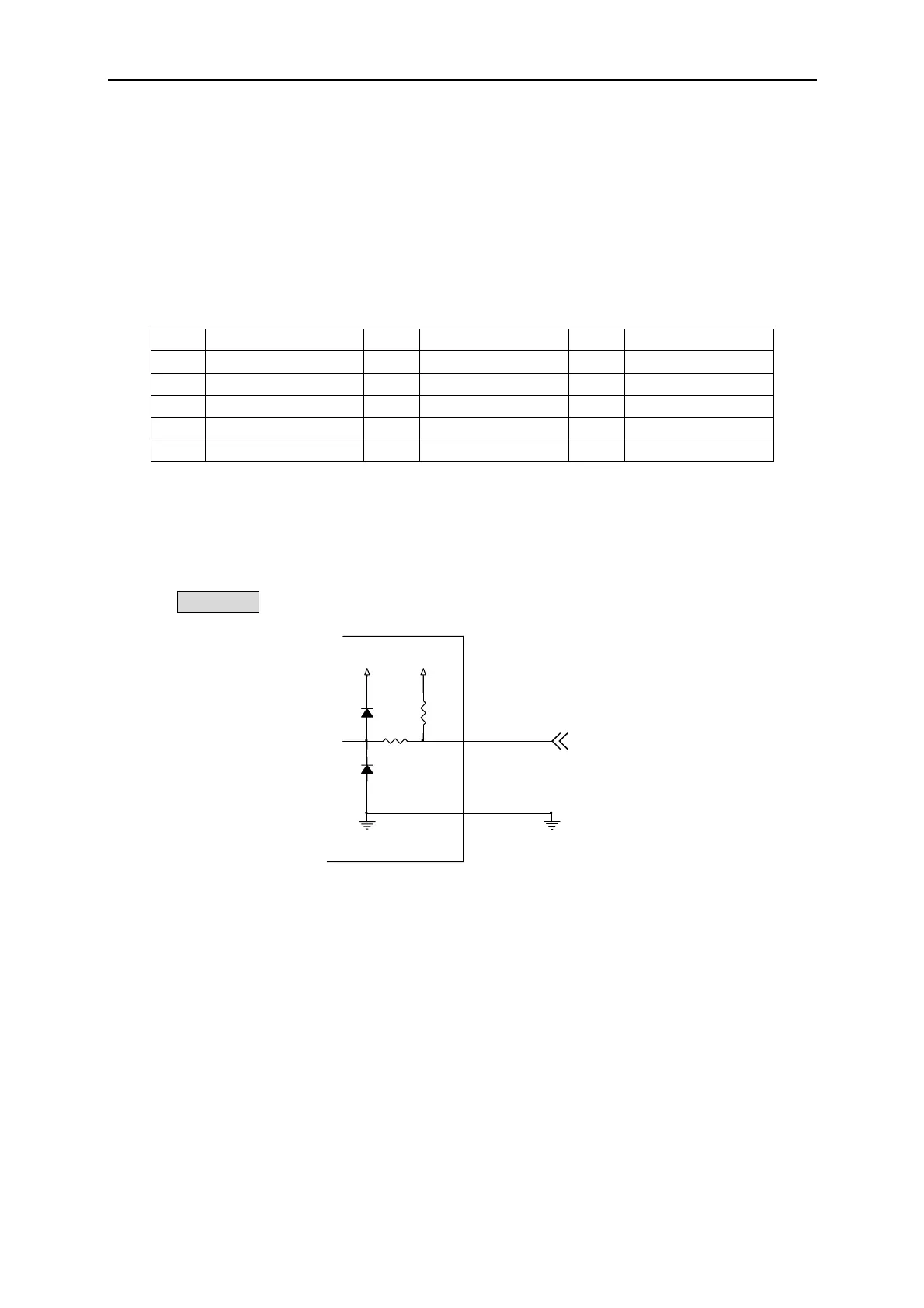
Limit Trigger Connection
Figure A-1 shows the connection of Limit Trigger. 66200 Series Power Meter defines the
Limit Trigger as falling edge trigger. Ground the 8
th
pin can trigger it. The trigger is same as
pressing Trig/Enter on the front panel.
GND
1K
GND
+5V+5V
Pin 8
1KDIODE
DIODE
Limit Trig
Figure A-1
Connection of Limit Trigger
Is Trigger Connection (66202 only)
Figure A-2 shows the connection of Is Trigger. 66202 Power Meter defines the Is Trigger as
falling edge trigger.
A-1
 Loading...


