Digital Power Meter 66200 Series User’s Manual
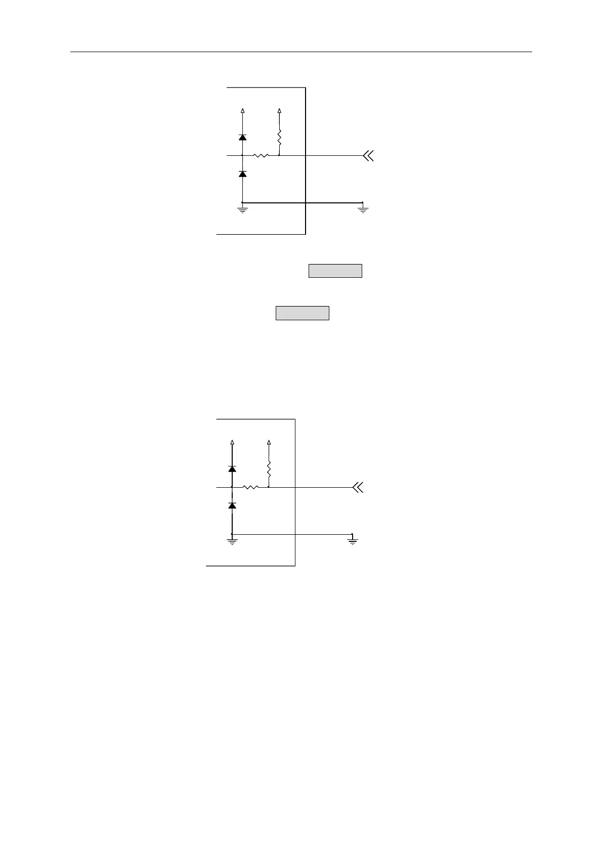
GND
1K
GND
+5V+5V
Pin 2
1KDIODE
DIODE
Is Trig
Figure A-2 Connection of Limit Trigger
Users can use external TTL signal to replace the Trig/Enter function on the front panel. First,
set the Is/Trig function following the steps 1~8 described in section 4.4.4 Is/Trig Function.
Next, set the AC current display to Is. Last ground the pin 2 can trigger it for inrush current
test. Every trigger is same as pressing the Trig/Enter key on the front panel.
Reserve TTL1-Reserve TTL3 Connection
Figure A-3 shows the connection of Reserve TTL1-Reserve TTL3. 66200 Series Power
Meter keeps the Reserve TTL1 -Reserve TTL3 for receiving TTL signal.
GND
1K
GND
+5V+5V
Pin 3,5,7
1KDIODE
DIODE
Reverse TTL1 -
ReserveTTL3
Figure A-3 Connection of Reserve TTL1-Reserve TTL3
Reserve TTL4-Reserve TTL5 Connection
Figure A-4 shows the connection of Reserve TTL4-Reserve TTL5. 66200 Series Power
Meter keeps the ReserveTTL4 -Reserve TTL5 for outputting TTL signal.
A-2
 Loading...


