Appendix A Using Control Signal Input/Output Terminal
GND
1K
GND
+5V
Pin 10,13
DIODE
DIODE
Reverse TTL4 -
Reverse TTL5
1K
+5V
1K
+5V
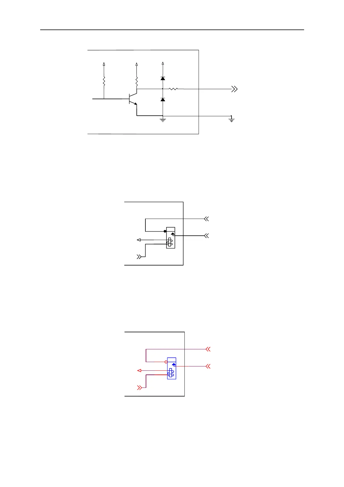
Figure A-4 Connection of Reserve TTL4-Reserve TTL5
Pass + / Pass – Connection
Figure A-5 shows the connection of Pass + / Pass –. Pass + / Pass – output is the two
terminals of a one-gate Relay as shown above. When running GO/NG if the test result is
Pass the Relay will short-circuit. The Relay specification is 200VDC/0.5A Max.
Pass+
4
3
1
2
Pin 15
Pass
Pin 14
Pass-
+5V
Figure A-5 Connection of Pass + / Pass –
Fail + / Fail – Connection
Figure A-6 shows the connection of Fail + / Fail –. Fail + / Fail – output is the two terminals
of a one-gate Relay as shown above. When running GO/NG if the test result is Fail the Relay
will short-circuit. The Relay specification is 200VDC/0.5A Max.
4
3
1
2
Pin 12
Pin 11
+5V
Fail+
Fail
Fail-
Figure A-6 Connection of Fail + / Fail –
A-3
 Loading...


