Digital Power Meter 66200 Series User’s Manual
4.2.2 Connecting with A662003 Fixture
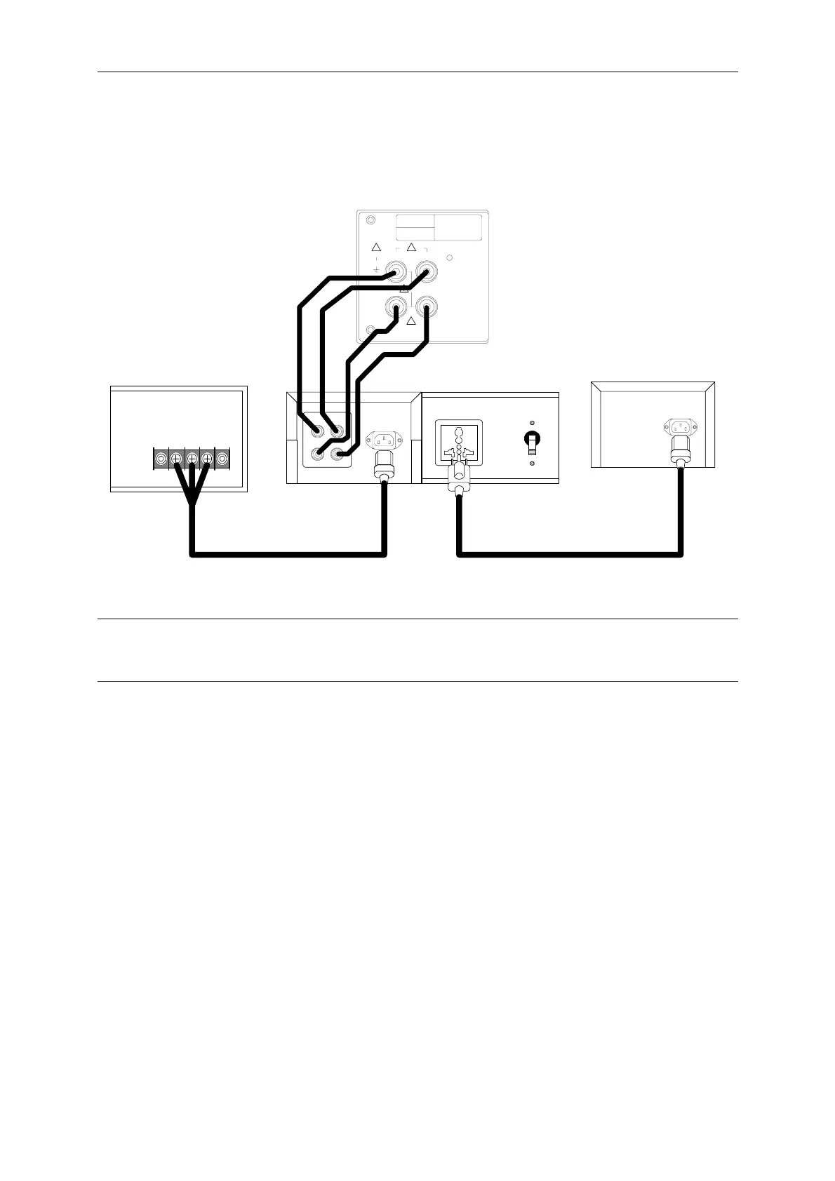
Figure 4-2 shows the connection of 66200 Series Digital Power Meter and A662003 fixture.
MODEL NO.
SERIAL NO.
CAT II
ALL INPUT
500Vrms
500Vrms
500Vrms
20Arms
V+ V-
I+ I-
! !
!
!
66200
AC Source
UUT
LN
G
250V / 15A
AC IN
I+ I-
V-V+
To Power Meter
Chrom
a
MEASUREMENT TEST
FIXTURE
SWITCH
250V / 15A
A662003
Figure 4-2 Connection of 66200 Series Digital Power Meter and A662003 Fixture
aCAUTION
Be sure the connecting cable of voltage and current are in correct position as it may cause the
internal circuit to burnout if connected mistakenly.
4.3 Test Function & Operation
When the Power Meter is powered on all LEDs on the front panel will be on for 3 seconds at
the same time and users can check if they are acting normally. The Power Meter will set the
panel display to its initial settings automatically where the voltage and current range are set to
AUTO after 3 seconds.
Before powering off the 66200 Series Power Meter, it will automatically save all parameter
settings to internal flash (not including the voltage/current range selection), so that all settings
will be resumed when power-on next time.
There are 4 display areas on the front panel of Power Meter. They are AC Voltage, AC
Current, Power and Special Parameters readouts. Their functions and operation procedures
are explained below.
4-2
 Loading...


