55
Instruction Manual
CVM-C4
7�3�3�- DIGITAL INPUTS
All the addresses of Modbus memory are in Hexadecimal.
For these variables is implemented the Function 0x02�
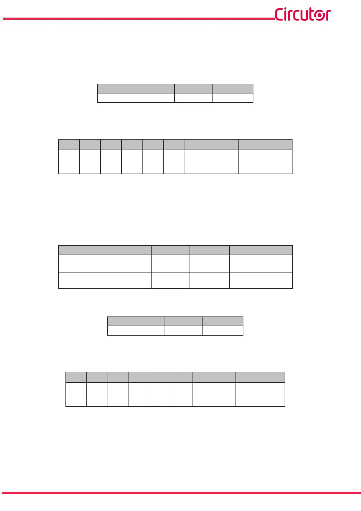
Table 18:Modbus Memory Map (Table 6)
Parameter Format Address
Digital inputs bit 0000
The format of the parameter is shown in Table 19:
Table 19: Variable format: Digital inputs�
Bit 7 Bit 6 Bit 5 Bit 4 Bit 3 Bit 2 Bit 1 Bit 0
0 0 0 0 0 0
Digital input 2
1: Closed
0: Open
Digital input 1
1: Closed
0: Open
7�3�4�- REMOTE CONTROL OUTPUT (Relay output)
All the addresses of Modbus memory are in Hexadecimal.
For these variables is implemented the Function 0x05:
Table 20: Modbus Memory Map (Table 7)
Parameter Format Address Value
Remote control, Relay output 1 bit 0000
0000: Open
FF00: Closed
Remote control, Relay output 2 bit 0001
0000: Open
FF00: Closed
Function 0x0F, multiple relay control:
Table 21: Modbus Memory Map (Table 8)
Parameter Format Address
Remote control bit 0000
The format of the parameter is shown in Table 22:
Table 22: Variable format: Remote control�
Bit 7 Bit 6 Bit 5 Bit 4 Bit 3 Bit 2 Bit 1 Bit 0
0 0 0 0 0 0
Relay 2
1: Closed
0: Open
Relay 1
1: Closed
0: Open