57
Instruction Manual
CVM-C4
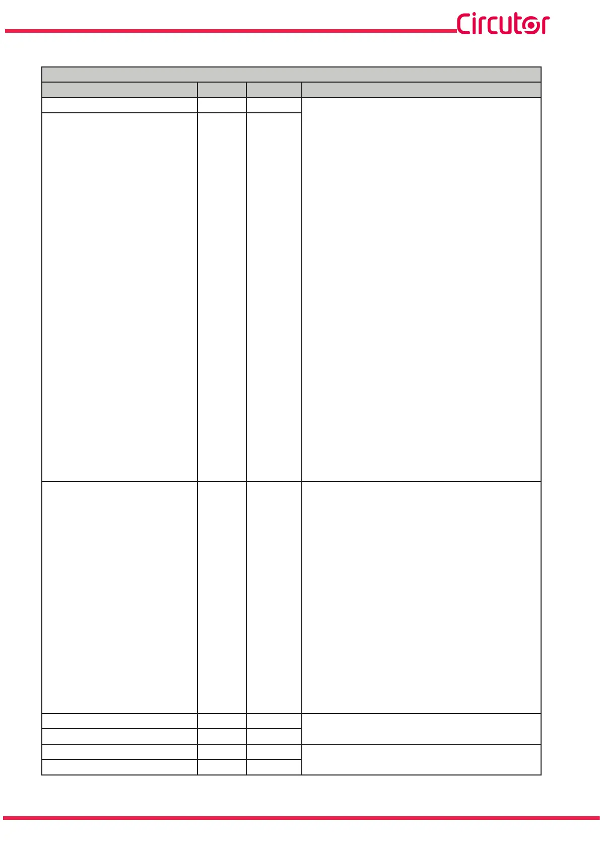
Table 25 (Continued): Modbus Memory Map: Relay Outputs�
Relay outputs
Variable Format Address Valid data range
Relay 1 alarm parameter int 81C 0: Active alarm when the Phase - Neutral voltage is
higher than the alarm value (Un. H).
1: Active alarm when the Phase - Neutral voltage is
lower than the alarm value (Un. L).
2: Active alarm when the Phase - Phase voltage is
higher than the alarm value (UL. H).
3: Active alarm when the Phase - Phase voltage is
lower than the alarm value (UL. L).
4: Active alarm when the current is higher than the
alarm value (i. H).
5: Active alarm when the current is lower than the
alarm value (i. L).
6: Active alarm when the active power is higher than
the alarm value (P. H).
7: Active alarm when the active power is lower than
the alarm value (P. L).
8: Active alarm when the reactive power is higher
than the alarm value.q. H).
9: Active alarm when the reactive power is lower
than the alarm value (q. L).
10: Active alarm when the apparent power is higher
than the alarm value (S. H).
11: Active alarm when the apparent power is lower
than the alarm value (S. L).
12: Active alarm when the power factor is higher
than the alarm value (PF. H).
13: Active alarm when the power factor is lower than
the alarm value (PF. L).
14: Active alarm when the frequency is higher than
the alarm value (F. H).
Relay 2 alarm parameter int 824
15: Active alarm when the frequency is lower than
the alarm value (F. L).
16: Active alarm when the THD voltage is higher
than the alarm value (UtH. H).
17: Active alarm when the THD voltage is lower than
the alarm value (UTH. L).
18: Active alarm when the THD current is higher
than the alarm value (itH. H).
19: Active alarm when the THD current is lower than
the alarm value (iTH. L).
20: Active alarm when digital input 1 is connected
(di-1).
21: Active alarm when digital input 1 is disconnected
(di-0)
22: Active alarm when digital input 1 is connected
(d2-1).
23: Active alarm when digital input 1 is disconnected
(d2-0)
Relay 1 alarm value oat 81D - 81E
See valid data ranges in section “6.3.4.- ALARM VA-
LUE"
Relay 2 alarm value oat 825 - 826
Relay 1 hysteresis oat 81F - 820
See valid data ranges in section “6.3.5.- HYSTERE-
SIS”
Relay 2 hysteresis oat 827 - 828