1-7
Cisco Aironet 1552 Series for Hazardous Locations Installation Guide
Chapter 1 Overview
Hardware Features
• Multiple Radio Operation, page 1-14
• Antenna Configurations, page 1-15
• Multiple Power Sources, page 1-19
• Ethernet (PoE) Ports, page 1-20
• Fiber Option, page 1-20
• Metal Enclosure, page 1-21
• Optional Hardware, page 1-21
Connectors
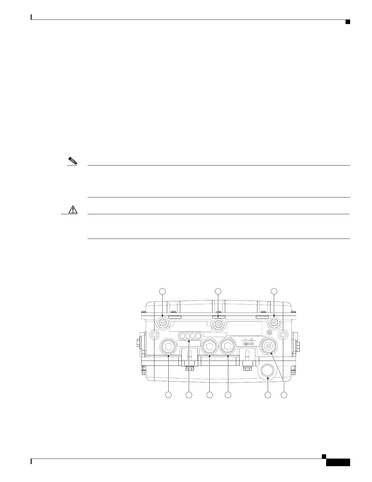
Figure 1-1 through Figure 1-6 show the access point connectors for each model. Figure 1-7 through
Figure 1-9 show the external antenna Type N connectors.
Note The illustrations in this document show all available connections for the access point. Unused
connections are capped with a connector plug to ensure the watertight integrity of the access point.
Liquid-tight adapters are provided for connector openings, which can be installed before or after
deploying the access point.
Caution The liquid-tight adapter(s) supplied in the kit are IP68/69 certified with .200 to .350 diameter cables but
not ATEX certified or hazardous locations compliant. The installer must use cable glands appropriate to
the installation.
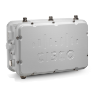
1552H
Figure 1-1 Access Point Model AIR-CAP1552H-x-K9 Bottom Connectors