1-8
Cisco Aironet 1552 Series for Hazardous Locations Installation Guide
Chapter 1 Overview
Hardware Features
Note Antenna ports 1, 2, and 3 are not shown in Figure 1-1. These ports are reserved for future use and are
located on the top of the access point.
1552SA/SD
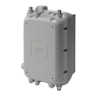
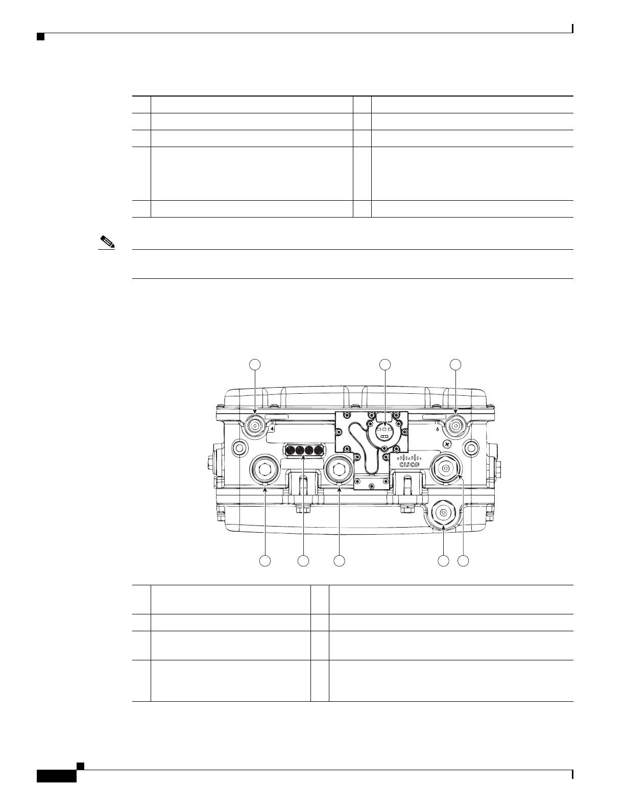
Figure 1-2 Access Point Model AIR-CAP1552SA/SD-x-K9 Bottom Connectors
1 Antenna port 4 6 Fiber port (PG 13.5 thread)
2 Antenna port 5 7 PoE Out port (PG 13.5 thread)
3 Antenna port 6 8 LEDs (Status, Up Link, RF1, RF2)
4 AC power entry port (1/2-NPT thread) for
model AIR-CAP1552H-x-K9 only
or
Cable Gland entry (1/2-NPT thread)
9 PoE In port (PG 13.5 thread) for data cable
(outdoor cat 5 STP cable)
5 Not used
4
1 32
568 7
331096
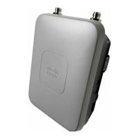
1
Antenna port 4 (ISA100 Wireless
and WirelessHART)
5 Not used
2 IR window 6 PoE Out port - (PG13.5 Thread)
3 Antenna port 6 (ISA100 Wireless
and WirelessHART RX)
7 LEDs (Status, Up Link, RF1, RF2)
4 AC (1552SA) or 24 VDC (1552SD)
power input port and fiber backhaul
port - (1/2NPT thread)
8 Copper Ethernet - (PG13.5 Thread)