1-11
Cisco Aironet 1552 Series for Hazardous Locations Installation Guide
Chapter 1 Overview
Hardware Features
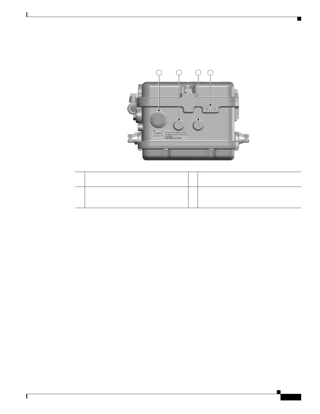
DC Power Connector
Figure 1-6 Access Point DC Power Connector and Ground Lug (All Models)
1552 Antenna Ports
Figure 1-7 shows the antenna port locations for model AIR-CAP1552H-x-K9.
1 12 VDC non-hazardous locations input port
(PG 13.5 thread size)
3 Bracket mounting hole (M8x1.25 x 12mm dp)
2 Bracket mounting hole (M8x1.25 x 12mm dp) 4 Ground lug location (connection for earth
grounding (minimum VD 16 mm, 6 awg)
(M4x.7 .30 THD Depth)