A-4
Cisco 2600 Series Routers Hardware Installation Guide
OL-2171-02
Appendix A Troubleshooting the Router
Reading the LEDs
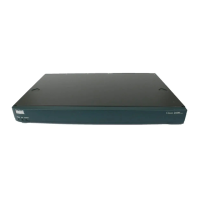
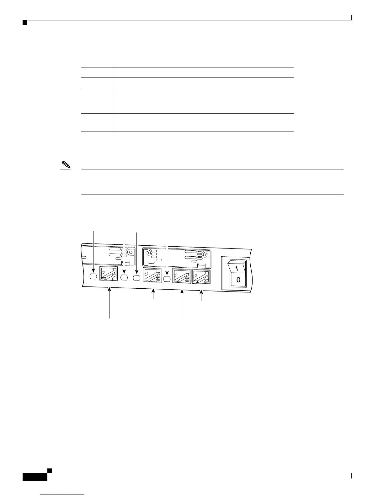
Figure A-2 through Figure A-7 show the location of the Cisco 2600 series rear-panel LEDs. Table A-3
and Table A-4 describe these LEDs.
Note Not all router models are shown in these illustrations. The speed and number of Ethernet and
Token Ring interfaces varies depending on the router model. LED labels and functionality will also
vary depending on the router model.
Figure A-3 Cisco 2611—Rear-Panel LEDs
Table A-2 Cisco 2691—Front-Panel LED Descriptions
LED Description
Power On—Power is applied to the router.
SYS/RPS Rapid blinking—System is booting
Slow blinking—System error
On—System OK
Activity Off—No system activity
Blinking—System activity
H11584
SEE MANUAL BEFORE INSTALLATION
SERIAL 1
SERIAL 0
CONN
CONN
WIC
2A/S
SEE MANUAL BEFORE INSTALLATION
SERIAL 1
SERIAL 0
CONN
WIC
2A/S
Cisco 2611
W0
AUX
CONSOLE
ETHERNET 0/0
ACT
LINKACTETHERNET 0/1LINK
Ethernet 0/0
10BASE-T
port (RJ-45)
Ethernet 0/1
10BASE-T
port (RJ-45)
Auxiliary
port (RJ-45)
Console
port (RJ-45)
Link
LED
ACT
LED
Link
LED
ACT
LED
 Loading...