2-2
Cisco TelePresence System 3200
OL-14521-01
Chapter 2 Building the Display Assembly
Parts List
Caution The display structures are unstable during assembly. Use caution, and support all structures as required.
Caution Some system components have metal and plastic edges with hard angles. These edges are exposed until
you complete system assembly. Use caution when you move around the system during assembly to avoid
contact with any exposed system edges.
Warning
Only trained and qualified personnel should be allowed to install, replace, or service this equipment.
Note The directions left and right refer to the assembly as you face the Plasma displays.
Note Before you start to build the structure, make sure that the floor in the installation room is level. An
uneven floor can make it difficult or, in severe cases, impossible to align the plasma displays after you
build the structure and mount the displays.
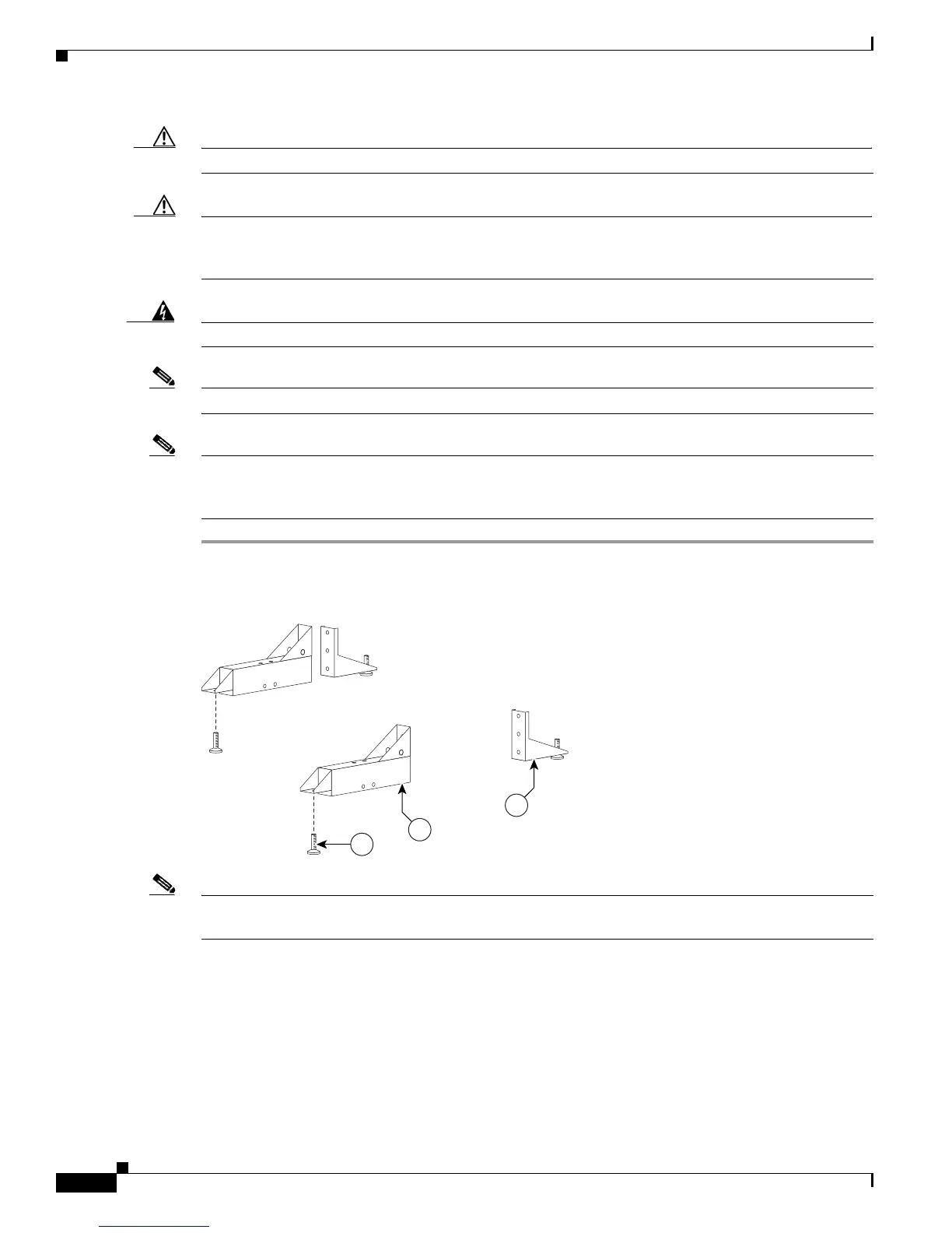
Step 1 Attach the Leveling feet to the Rear and Front Foot stabilizers.
Figure 2-1 Leveling feet
Note Figure 2-8 shows the correct positioning of the display structure; keep this in mind as you build the
structure.