4-3
Cisco TelePresence System 3200
OL-14521-01
Chapter 4 Building the Display Shelf Assembly
Parts List
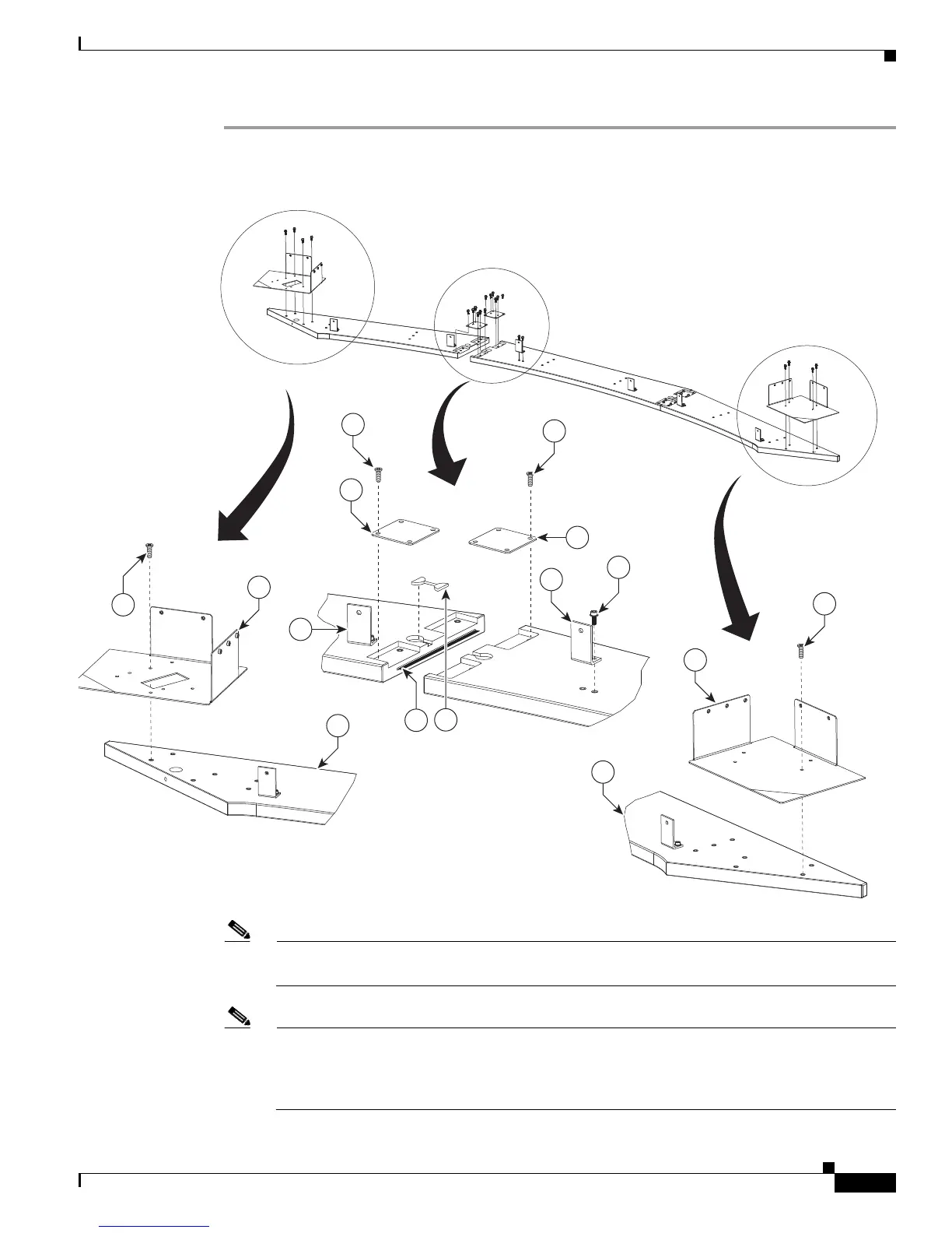
Step 1 Attach the Display shelf hardware.
Figure 4-1 Display shelf hardware
Note The Right Accessory Cabinet attachment bracket (marked “6” in the illustration), has a central
rectangular hole that differentiates it from the Left Accessory Cabinet attachment bracket.
Note This illustration describes the hardware used to attach the three Display shelves and the
hardware used to attach additional assemblies in
Chapter 8, “Assembling the Remaining
Cisco TelePresence Elements.” The Display shelves should be attached individually to the
Display structures, as illustrated in Figure 4-2, Figure 4-3, and Figure 4-4.
12
5
3
1
12
6
205467
8
9
12
10
11
9
14
14
8