7-14
Firepower 7000 and 8000 Series Installation Guide
Chapter 7 Hardware Specifications
Firepower 7000 Series Devices
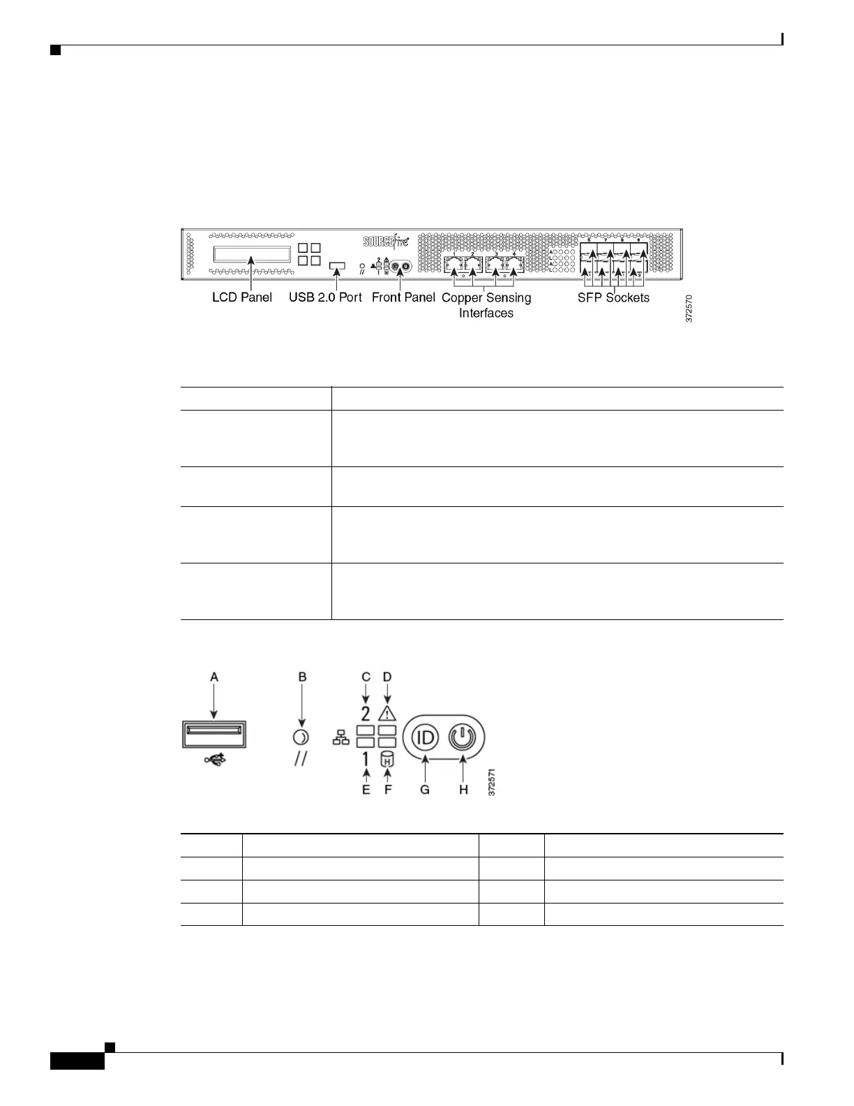
Firepower 7115, 7125, and AMP7150 Chassis Front View
The front of the chassis contains the LCD panel, USB port, front panel, copper sensing interfaces, and
SFP sockets.
Figure 7-11 Firepower 7115, 7125, and AMP7150 (Chassis: GERY-1U-8-4C8S-AC) Front View
The following table describes the features on the front of the appliance.
Figure 7-12 Firepower 7115, 7125, and AMP7150 Front Panel
The front panel of the chassis houses LEDs, which display the system’s operating state. The following
table describes the LEDs on the front panel.
Table 7-22 Firepower 7115, 7125, and AMP7150 System Components: Front View
Feature Description
LCD panel Operates in multiple modes to configure the device, display error messages,
and view system status. For more information, see Using the LCD Panel on
a Firepower Device, page 6-1.
Front panel USB 2.0
port
Allows you to attach a keyboard to the device.
Front panel Houses LEDs that display the system’s operating state, as well as various
controls, such as the power button. For more information, see
Figure 7-12Firepower 7115, 7125, and AMP7150 Front Panel, page 7-14.
Sensing interfaces Contain the sensing interfaces that connect to the network. For more
information, see Firepower 7115, 7125, and AMP7150 Sensing Interfaces,
page 7-16.
Table 7-23 Firepower 7115, 7125, and AMP7150 Front Panel Components
A USB 2.0 connector E NIC1 activity LED
B Reset button F Hard drive activity LED
C NIC2 activity LED G ID button
D System status LED H Power button and LED