26-3
Cisco 7600 Series Router Cisco IOS Software Configuration Guide, Release 12.2SX
OL-4266-08
Chapter 26 Configuring IP Unicast Layer 3 Switching
Understanding How Layer 3 Switching Works
If Source A and Destination B are in different subnets and Source A sends a packet to the MSFC to be
routed to Destination B, the router recognizes that the packet was sent to the Layer 2 (MAC) address of
the MSFC.
To perform Layer 3 switching, the router rewrites the Layer 2 frame header, changing the Layer 2
destination address to the Layer 2 address of Destination B and the Layer 2 source address to the Layer 2
address of the MSFC. The Layer 3 addresses remain the same.
In IP unicast and IP multicast traffic, the router decrements the Layer 3 TTL value by 1 and recomputes
the Layer 3 packet checksum. The router recomputes the Layer 2 frame checksum and forwards (or, for
multicast packets, replicates as necessary) the rewritten packet to Destination B’s subnet.
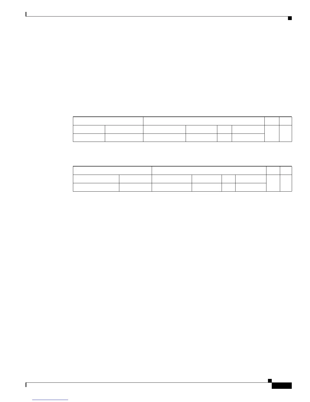
A received IP unicast packet is formatted (conceptually) as follows:
After the router rewrites an IP unicast packet, it is formatted (conceptually) as follows:
Hardware Layer 3 Switching Examples
Figure 26-1 on page 26-4 shows a simple network topology. In this example, Host A is on the Sales
VLAN (IP subnet 171.59.1.0), Host B is on the Marketing VLAN (IP subnet 171.59.3.0), and Host C is
on the Engineering VLAN (IP subnet 171.59.2.0).
When Host A initiates an HTTP file transfer to Host C, Hardware Layer 3 switching uses the information
in the local forwarding information base (FIB) and adjacency table to forward packets from Host A to
Host C.
Layer 2 Frame Header Layer 3 IP Header Data FCS
Destination Source Destination Source TTL Checksum
MSFC MAC Source A MAC Destination B IP Source A IP n calculation1
Layer 2 Frame Header Layer 3 IP Header Data FCS
Destination Source Destination Source TTL Checksum
Destination B MAC MSFC MAC Destination B IP Source A IP n-1 calculation2