28-3
Cisco 7600 Series Router Cisco IOS Software Configuration Guide, Release 12.2SX
OL-4266-08
Chapter 28 Configuring IPv4 Multicast Layer 3 Switching
Understanding How IPv4 Multicast Layer 3 Switching Works
These commands affect the Layer 3 switching cache entries:
• When you clear the multicast routing table using the clear ip mroute command, all multicast Layer
3 switching cache entries are cleared.
• When you disable IP multicast routing on the MSFC using the no ip multicast-routing command,
all multicast Layer 3 switching cache entries on the PFC are purged.
• When you disable multicast Layer 3 switching on an individual interface basis using the no mls
ipmulticast command, flows that use this interface as the RPF interface are routed only by the
MSFC in software.
Layer 3-Switched Multicast Packet Rewrite
When a multicast packet is Layer 3 switched from a multicast source to a destination multicast group,
the PFC and the DFCs perform a packet rewrite that is based on information learned from the MSFC and
stored in the adjacency table.
For example, Server A sends a multicast packet addressed to IP multicast group G1. If there are members
of group G1 on VLANs other than the source VLAN, the PFC must perform a packet rewrite when it
replicates the traffic to the other VLANs (the router also bridges the packet in the source VLAN).
When the PFC receives the multicast packet, it is (conceptually) formatted as follows:
The PFC rewrites the packet as follows:
• Changes the source MAC address in the Layer 2 frame header from the MAC address of the host to
the MAC address of the MSFC (This is the burned-in MAC address of the system. This MAC address
will be the same for all outgoing interfaces and cannot be modified. This MAC address can be displayed
using the show mls multicast statistics command.)
• Decrements the IP header Time to Live (TTL) by one and recalculates the IP header checksum
The result is a rewritten IP multicast packet that appears to have been routed. The PFC replicates the
rewritten packet onto the appropriate destination VLANs, where it is forwarded to members of IP
multicast group G1.
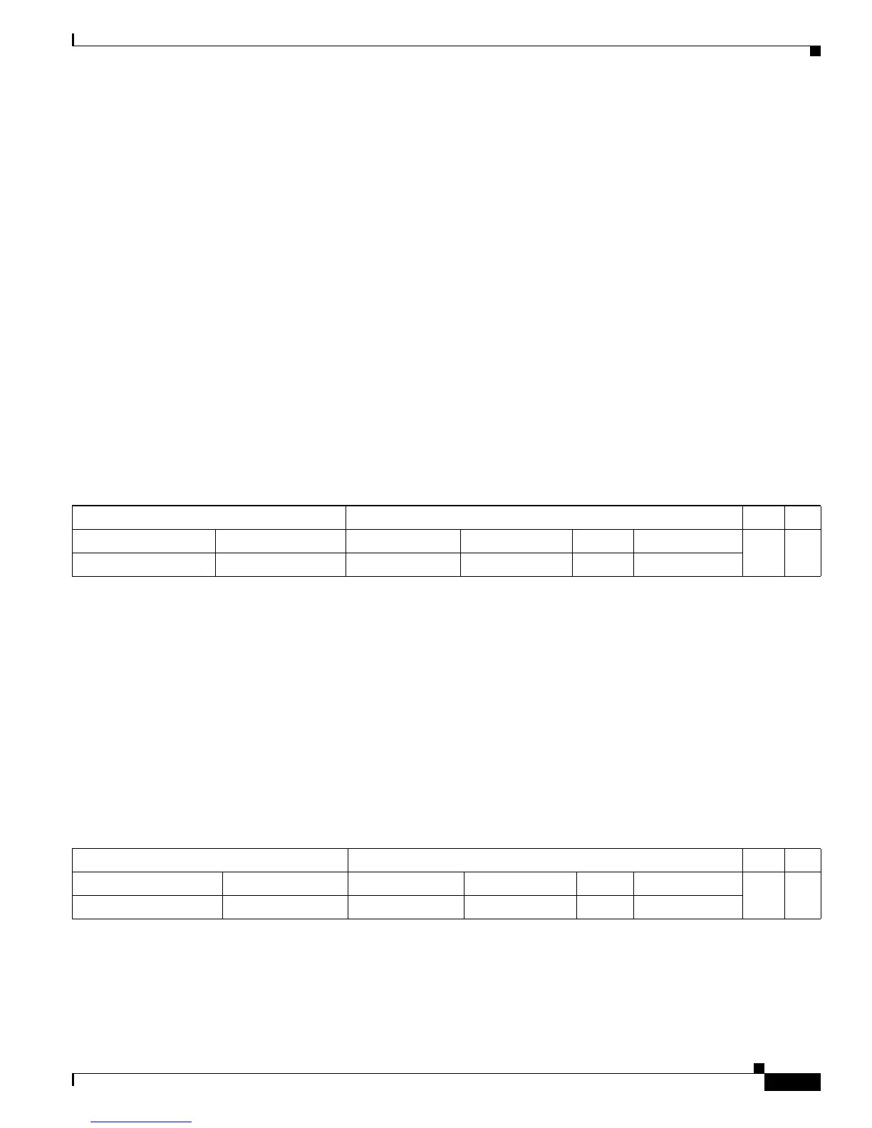
After the PFC performs the packet rewrite, the packet is (conceptually) formatted as follows:
Layer 2 Frame Header Layer 3 IP Header Data FCS
Destination Source Destination Source TTL Checksum
Group G1 MAC
1
1. In this example, Destination B is a member of Group G1.
Source A MAC Group G1 IP Source A IP n calculation1
Frame Header IP Header Data FCS
Destination Source Destination Source TTL Checksum
Group G1 MAC MSFC MAC Group G1 IP Source A IP n–1 calculation2