2-18
Cisco Integrated Services Router Hardware Installation Guide
Chapter 2 Installing the Router
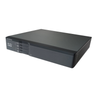
Installing the Cisco 810 ISR
Step 4 Route the cables through the bracket before you attach the bracket to the ceiling.
Step 5 Route the cables through the main cable access hole and then through the smaller access hole as shown
in Figure 2-16.
Step 6 (Optional) Use the ground screw to attach the building ground wire to the ground location on the base
of the router. See the “Grounding the Cisco 812 ISR” section on page 2-18 for the general grounding
instructions.
Step 7 Connect the Ethernet and power cables to the router.
Step 8 Align the router feet over the keyhole mounting slots on the optional mounting bracket.
Step 9 Slide the router onto the optional mounting bracket until it clicks into place.
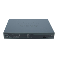
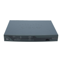
Grounding the Cisco 812 ISR
Grounding is not always required for indoor installations because the Cisco 812 ISR is classified as a
low-voltage device and does not contain internal power supplies. However, it is recommended that you
check your local and national electrical codes to see if grounding is a requirement. If grounding is
required in your area or you wish to ground your router, perform the following steps:
Warning
Use copper conductors only.
Statement 1025
Warning
This equipment must be grounded. Never defeat the ground conductor or operate the equipment in the
absence of a suitably installed ground conductor. Contact the appropriate electrical inspection
authority or an electrician if you are uncertain that suitable grounding is available.
Statement 1024
Warning
When installing or replacing the unit, the ground connection must always be made first and
disconnected last.
Statement 1046
Warning
This equipment needs to be grounded. Use a green and yellow 12 to 14 AWG ground wire to connect
the host to earth ground during normal use.
Statement 242
Step 1 Find a suitable building grounding point as close to the router as possible.
Step 2 Connect a user-supplied ground wire to the building grounding point. The wire should be a minimum of
#14AWG assuming a circuit length of 25 feet (30.5 cm). Consult your local electrical codes for
additional information.
Step 3 Route the ground wire to the router.
Step 4 Attach the wire to a suitable grounding ring lug.
Step 5 Crimp or solder the wire to the lug.
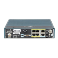
Step 6 Use a Phillips screwdriver to remove the existing 6-32 screw at the grounding location as shown in
Figure 2-17.
 Loading...