 Loading...
Do you have a question about the Cisco 860 Series and is the answer not in the manual?
| VPN Support | Yes |
|---|---|
| Firewall | Yes |
| QoS | Yes |
| Data Link Protocol | Ethernet, Fast Ethernet |
| Remote Management Protocol | SNMP, Telnet, HTTP, HTTPS |
| Operating System | Cisco IOS |
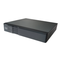
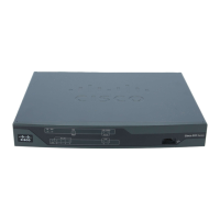
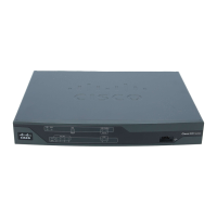
| Device Type | Router |
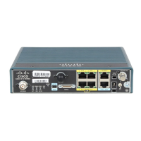
| WAN Interfaces | 1 x 10/100Base-TX - RJ-45 |
| LAN Interfaces | 4 x 10/100Base-TX - RJ-45 |
| Connectivity Technology | Wired |
| Network / Transport Protocol | IPSec, TCP/IP |
| Features | DHCP support, NAT support, VLAN support, IPv6 support |
| Compliant Standards | IEEE 802.3, IEEE 802.3u |