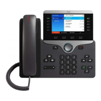
Figure 94: HV Power Tray Standby Mode Switch
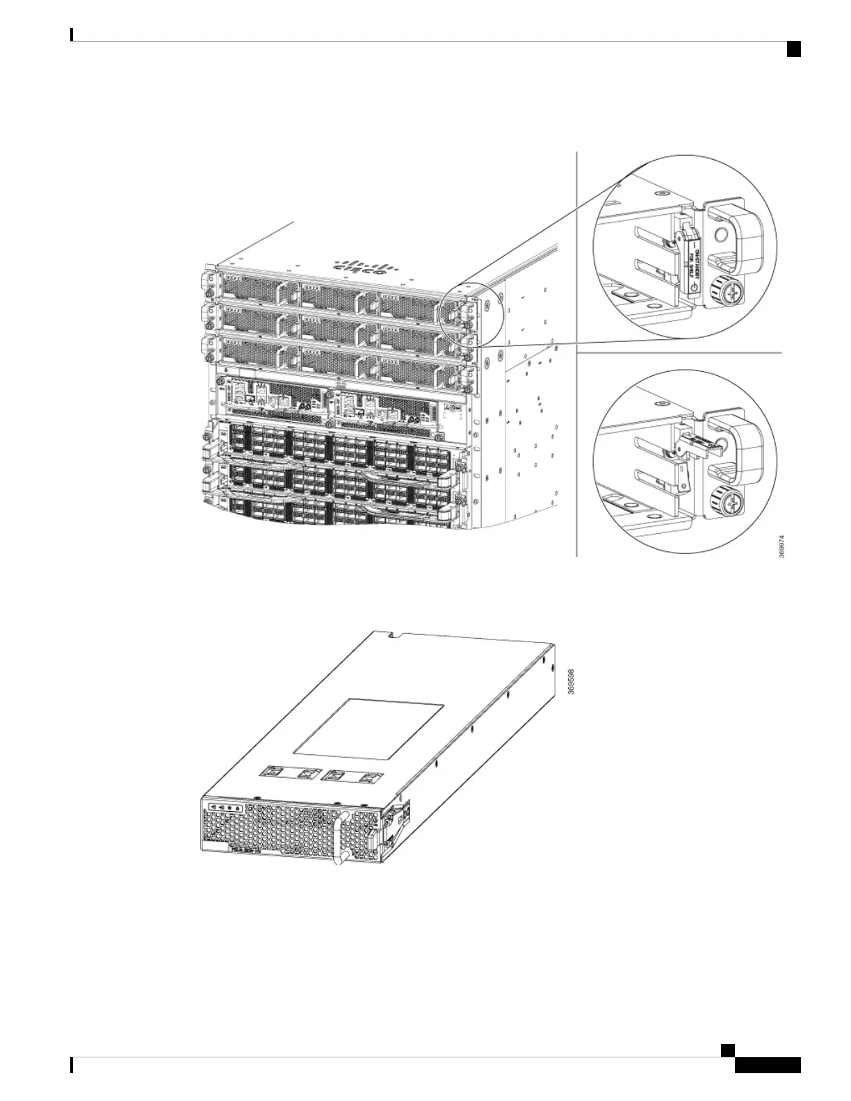
Step 2 Slide the power module out of its bay while supporting it with your other hand to remove it.
Figure 95: HV Power Supply
Step 3 Slide the new power module into the bay until it mates with its connector.
Hardware Installation Guide for Cisco 8800 Series Routers
131
Replace Chassis Components
Replace HVAC and HVDC Power Module
 Loading...