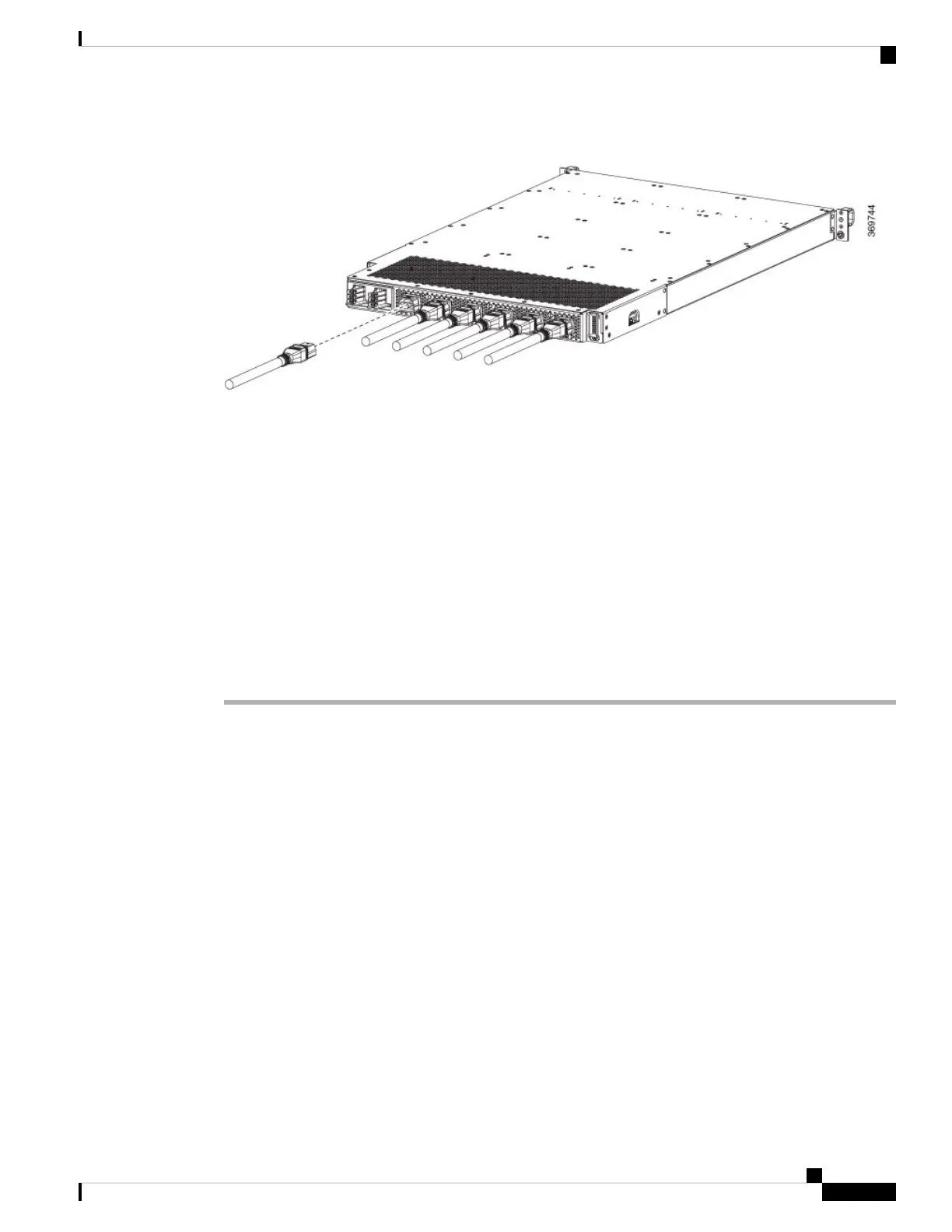
Figure 58: HVAC Power Connection
Step 3 For HVDC input, connect a Saf-D-Grid DC cable to a Saf-D-Grid receptacle, otherwise:
a) Connect the ground terminal ring on the power cable to the ground terminal on the DC power source and
secure it in place with a nut tightened to the appropriate torque setting for the terminal post.
b) Connect the negative terminal ring on the power cable to the negative (-) terminal on the DC power source
and secure it in place with a nut tightened to the appropriate torque setting for the terminal post.
c) Connect the positive terminal ring on the power cable to the negative (+) terminal on the DC power source
and secure it in place with a nut tightened to the appropriate torque setting for the terminal post.
Step 4 Verify that the Saf-D-Grid plug is plugged in completely to secure the built-in retaining latch.
Step 5 Turn on the circuit breaker for the HVAC or HVDC power source circuit.
If you use both inputs, the IN LED of the power supply is green. If you use only one input, the IN
LED is blinking green.
Note
Step 6 Turn on the switch of the power shelf to turn on the system.
What to do next
Use the power-mgmt redundancy-num-pms number command in config mode to convert the power module
redundancy from n+1 to n+x, specifying the number of redundant power modules that the you want to configure.
The total number of functioning power modules in the system is at least x number more than the number of
power modules that are needed to support the power required for all the cards in the system. The range is
0–11; 0 means that no power redundancy is required.
RP/0/RP0/CPU0:ios# config
RP/0/RP0/CPU0:ios(config)# power-mgmt redundancy-num-pms 2
RP/0/RP0/CPU0:ios(config)# commit
Tue Sep 24 09:03:22.889 UTC
Commit complete.
Use the hw-module attention-led location0/PM number command in config mode to enable and use the no
form of the command to disable the ID LED on the specified power supply.
RP/0/RP0/CPU0:ios# config
RP/0/RP0/CPU0:ios(config)# hw-module attention-led location 0/PT0-PM0
RP/0/RP0/CPU0:ios(config)# commit
Hardware Installation Guide for Cisco 8800 Series Routers
71
Powering on the Router
Connect HVAC/HVDC Power Supply to Power Source
 Loading...