1-7
Catalyst 2970 Switch Hardware Installation Guide
OL-6422-01
Chapter 1 Product Overview
Front Panel Description
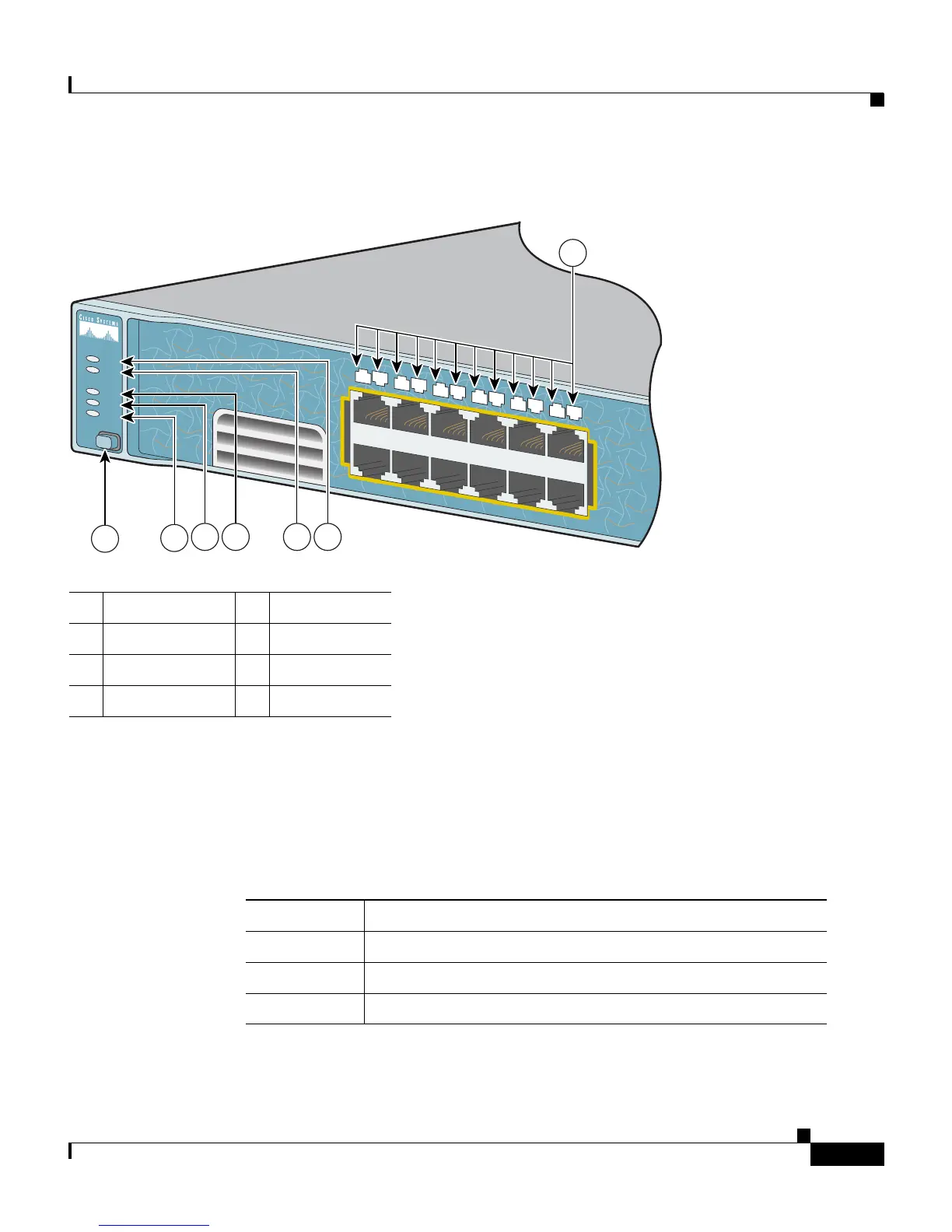
Figure 1-3 Catalyst 2970 Switch LEDs
System LED
The System LED shows whether the system is receiving power and is functioning
properly. Table 1-1 lists the LED colors and their meanings.
1 Mode button 5 RPS LED
2 Speed LED 6 System LED
3 Duplex LED 7 Port LEDs
4 Status LED
1X
2X
87619
SYST
RPS
STAT
DUPLX
SPEED
MODE
1X
2X
11X
12X
1
2
4
5
6
7
8
9
10
11
12
3
1
2
3 654
7
Table 1-1 System LED
Color System Status
Off System is not powered on.
Green System is operating normally.
Amber System is receiving power but is not functioning properly.