1-3
Catalyst 2970 Switch Hardware Installation Guide
OL-6422-01
Chapter 1 Product Overview
Front Panel Description
Front Panel Description
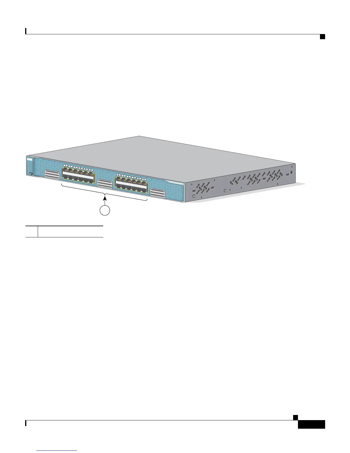
The 10/100/1000 ports on the Catalyst 2970G-24T switch are grouped in pairs.
The first member of the pair (port 1) is above the second member (port 2) on the
left, as shown in Figure 1-1. Port 3 is above port 4, and so on.
Figure 1-1 Catalyst 2970G-24T Switch Front Panel
The 10/100/1000 ports on the Catalyst 2970G-24TS switch are grouped in pairs.
The first member of the pair (port 1) is above the second member (port 2) on the
left, as shown in Figure 1-2. Port 3 is above port 4, and so on. The SFP module
slots are numbered 25 to 28.
1 10/100/1000 ports
87618
Catalyst 2970
S
E
R
IE
S
3
1
1X
2X
11X
12X
1
2
4
5
6
7
8
9
1
0
1
1
1
2
13X
14X
23X
24X
1
3
1
4
1
5
1
6
1
7
1
8
1
9
2
0
2
1
2
2
2
3
2
4
SYST
RPS
STAT
DUPLX
SPEED
M
O
D
E