Chapter 1 Product Overview
Rear Panel Description
1-12
Catalyst 2970 Switch Hardware Installation Guide
OL-6422-01
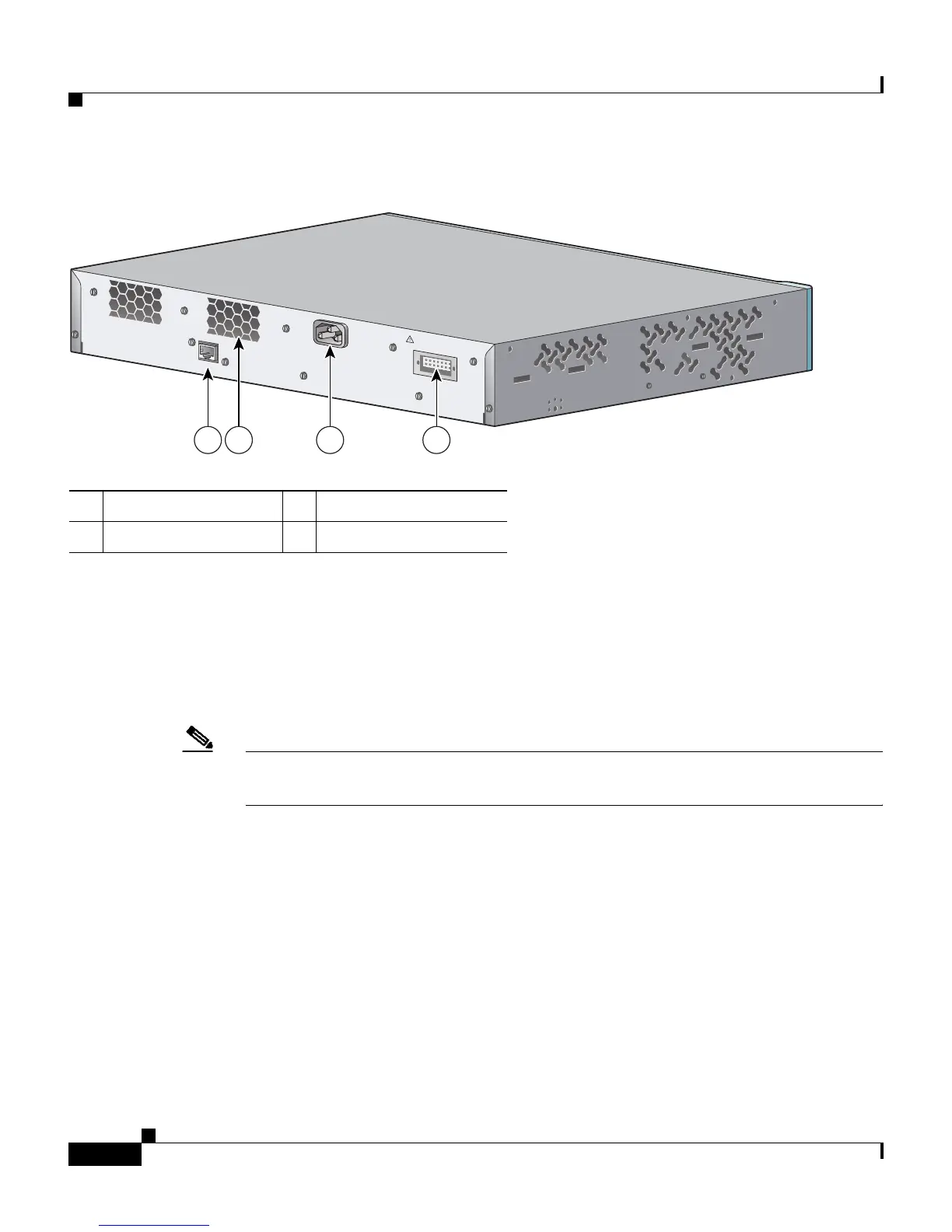
Figure 1-5 Catalyst 2970G-24TS Switch Rear Panel
Power Connectors
The switch is powered through the internal power supply. You can also connect
the Cisco RPS 675 to provide backup power if the switch internal power supply
should fail.
Note The Catalyst 2970 switch and the Cisco RPS 675 should be connected to the same
AC power source.
Internal Power Supply Connector
The internal power supply is an autoranging unit that supports input voltages
between 100 and 240 VAC. Use the supplied AC power cord to connect the AC
power connector to an AC power outlet.
1 RJ-45 console port 3 AC power connector
2 Fan exhaust 4 RPS connector
CONSOLE
DC INPUTS FOR REMOTE
POWER SUPPLY
SPECIFIED IN MANUAL
+12v @17a
1 2 3 4
97401