15-8
Catalyst 3550 Multilayer Switch Software Configuration Guide
78-11194-09
Chapter 15 Configuring 802.1Q and Layer 2 Protocol Tunneling
Understanding Layer 2 Protocol Tunneling
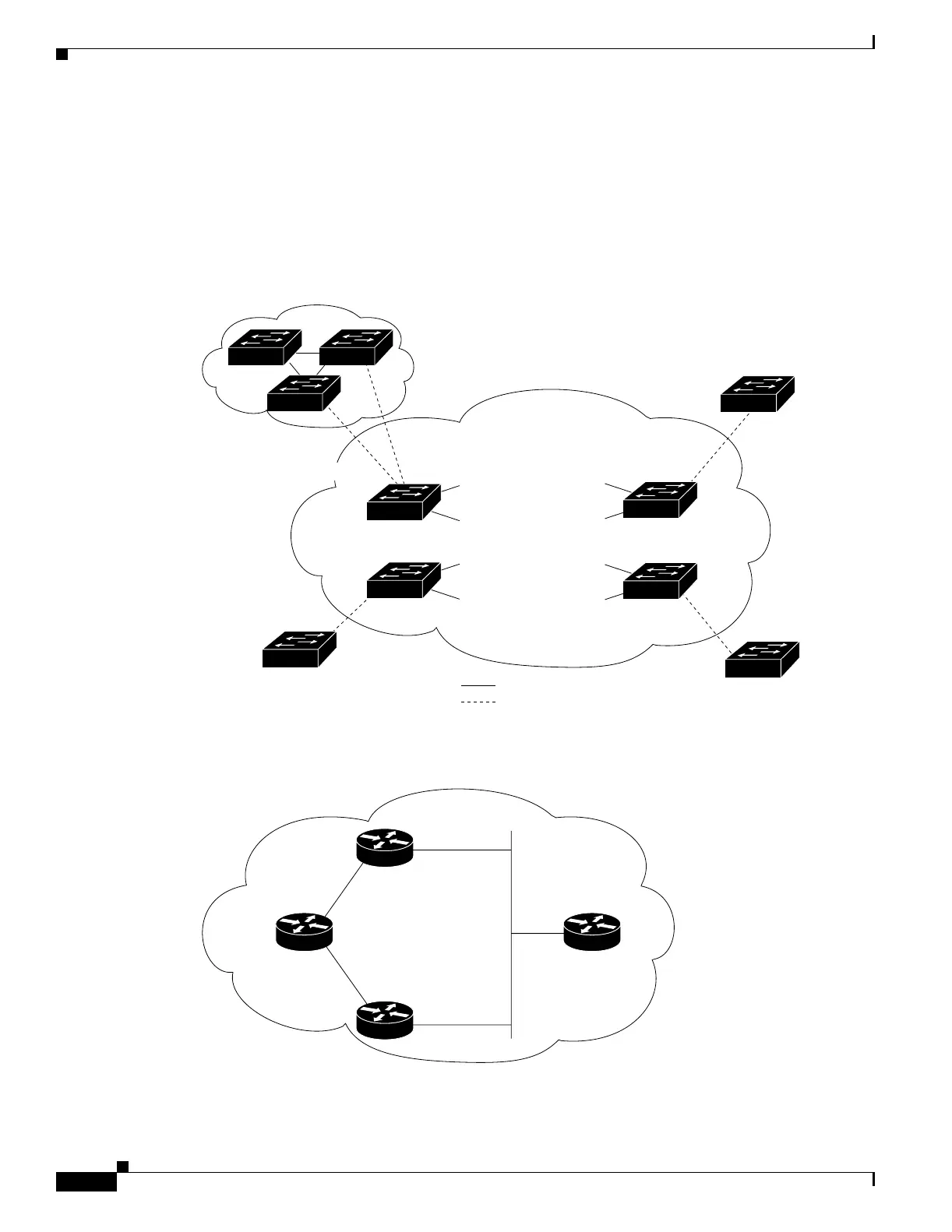
As an example, Customer A in Figure 15-4 has four switches in the same VLAN that are connected
through the SP network. If the network does not tunnel PDUs, switches on the far ends of the network
cannot properly run STP, CDP, and VTP. For example, STP for a VLAN on a switch in Customer A’s
Site 1 will build a spanning tree on the switches at that site without considering convergence parameters
based on Customer A’s switch in Site 2. This could result in the topology shown in Figure 15-5.
Figure 15-4 Layer 2 Protocol Tunneling
Figure 15-5 Layer 2 Network Topology without Proper Convergence
Customer A Site 2
VLANs 1 to 100
Customer B Site 2
VLANs 1 to 200
Customer B Site 1
VLANs 1 to 200
Customer A Site 1
VLANs 1 to 100
VLAN 30
Trunk
ports
Switch 1
Switch 1
Trunk
ports
VLAN 30
VLAN 40
Service
provider
74073
Trunk
Asymmetric link
VLAN 30
VLAN 40
Trunk
ports
Switch 2
Switch 3
Switch 4
Trunk
ports
74017
Customer A
virtual network
VLANs 1 to 100
 Loading...


