34-6
Catalyst 3550 Multilayer Switch Software Configuration Guide
78-11194-09
Chapter 34 Configuring IP Multicast Routing
Cisco Implementation of IP Multicast Routing
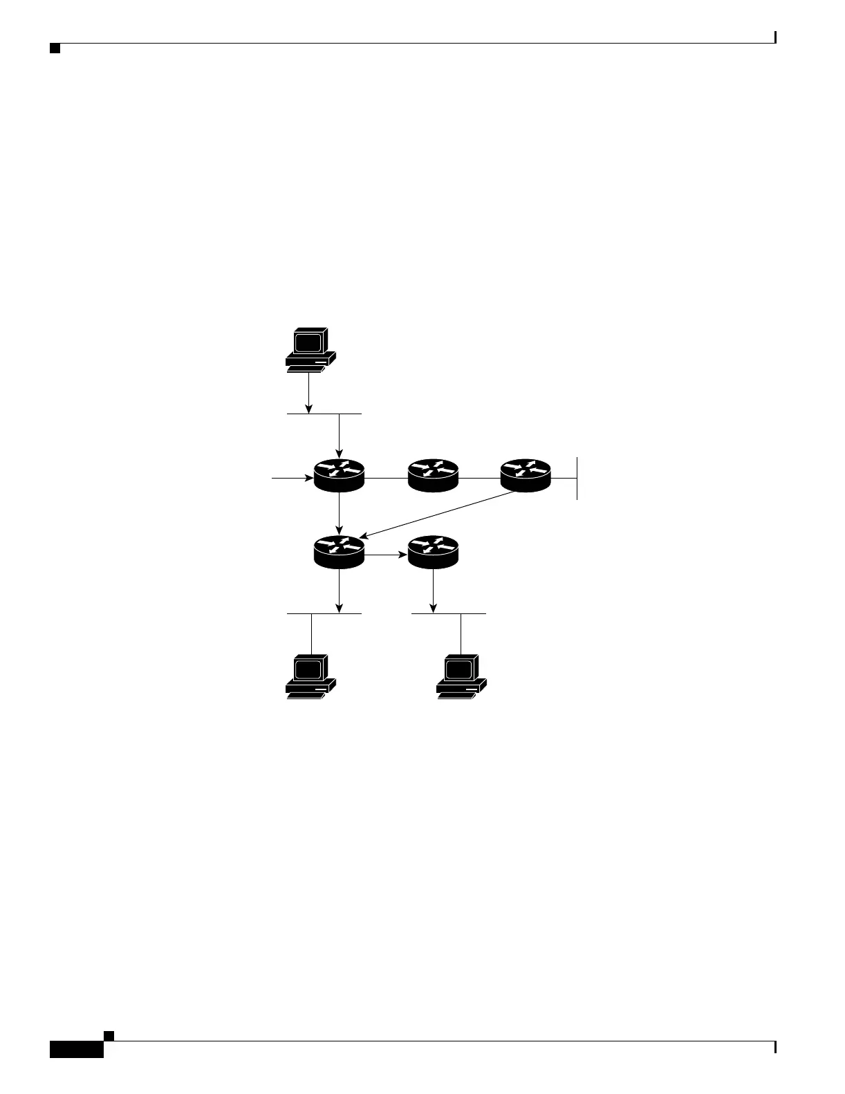
The simplest form of a multicast distribution tree is a source tree whose root is the source of the multicast
traffic and whose branches form a spanning tree through the network to the receivers. Because this tree
uses the shortest path through the network, it is also referred to as a shortest-path tree (SPT). A separate
SPT exists for every individual source sending to each group. The special notation of (S,G) (pronounced
S comma G) identifies an SPT where S is the IP address of the source and G is the multicast group
address.
Figure 34-4 shows an example of SPT for group 224.1.1.1 rooted at the source, Host A, and connecting
two receivers, Hosts B and C. The SPT notation for this group would be (194.1.1.1, 224.1.1.1).
Figure 34-4 Host A Shortest-Path Tree
If Host B is also sending traffic to group 224.1.1.1 and Hosts A and C are receivers, then a separate (S,G)
SPT would exist with the notation of (194.2.2.2, 224.1.1.1).
PIM DM employs only SPTs to deliver (S,G) multicast traffic by using a flood and prune method. It
assumes that every subnet in the network has at least one receiver of the (S,G) multicast traffic, and
therefore the traffic is flooded to all points in the network.
To avoid unnecessary consumption of network resources, PIM DM devices send prune messages up the
source distribution tree to stop unwanted multicast traffic. Branches without receivers are pruned from
the distribution tree, leaving only branches that contain receivers. Prunes have a timeout value associated
with them, after which the PIM DM device puts the interface into the forwarding state and floods
multicast traffic out the interface. When a new receiver on a previously pruned branch of the tree joins
a multicast group, the PIM DM device detects the new receiver and immediately sends a graft message
up the distribution tree toward the source. When the upstream PIM DM device receives the graft
message, it immediately puts the interface on which the graft was received into the forwarding state so
that the multicast traffic begins flowing to the receiver.
Host A
Source
194.1.1.1
224.1.1.1 Traffic
194.2.2.2
Host B
Receiver
194.3.3.3
Host C
Receiver
Router 1 Router 2
Router 5
Router 4
Router 3
45147