DescriptionSeconds Required to Trigger ModeMode
Causes the switch to start DHCP discovery
phase on the Vlan 1 interface.
6 to 10 secondsMedium Press
Causes the switch to erase its startup
configuration and reload. This in turn
causes the switch to revert to its Day 1
default configuration.
16 to 20Long Press
The setup LED displays the Express Setup mode for the initial configuration.
Table 3: Setup LED States
StatusColor
Switch is configured as a managed switch.Off
System is operating normally.Solid green
Switch is in initial setup, in recovery, or initial setup is incomplete.Blinking green
Switch failed to start initial setup or recovery because there is no available
switch port to connect the management station. Disconnect a device from a
switch port, and then press the Express Setup button.
Red
System LED
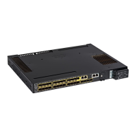
The system LED provides basic status about the health of the Cisco Catalyst IE9300 Rugged Series Switch.
Table 4: System LED
System StatusColor
System is not powered on.Off
Power-on self-test (POST) is in progress.Blinking green
System is operating normally.Green
System is receiving power but is not functioning properly.Red
Boot failure.Blinking red
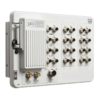
Power Supplies
The Cisco Catalyst IE9300 Rugged Series Switch supports two hot-swappable, redundant, load-sharing FRU
power supplies. It requires one power supply for system operation, and the second power supplies is optional
for redundancy. Both are installed on the back of the switch.
Cisco Catalyst IE9300 Rugged Series Switch Hardware Installation Guide
5
Cisco IE9300 Rugged Series Overview
System LED
 Loading...