EasyManuals Logo

Cisco D9854-I User Manual

Cisco D9854-I
440 pages
To Next Page IconTo Next Page
To Previous Page IconTo Previous Page
Page #242 background imageLoading...
Page #242 background image
Chapter 5 Web GUI Setup and Monitoring
218
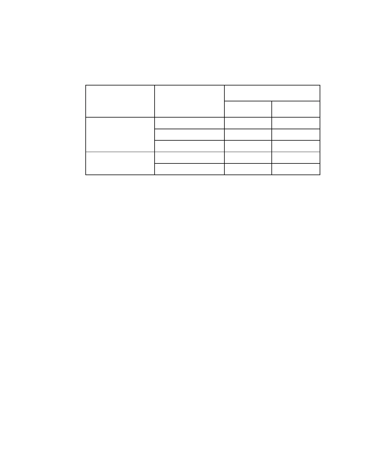
7 From the Relay Mode drop-down list, choose the relay mode that can be
programmed to respond to an Alarm state, Warning statue, or the state of one of
the eight cue trigger pins. The response is generated at the Cue Tone/Relay
output on the rear panel of the receiver. The following table shows what the
possible field settings are and their relationship to the receiver output:
Relay Mode
Condition
Relay Contact
NC - C
C-NO
Alarm
Unit Power Off
Open
Close
Alarm State
Open
Close
No Alarm
Close
Open
Trigger
Active (selected in PNC)
Close
Open
Inactive
Open
Close
8 If the Relay Mode is set to Trigger, choose the cue trigger bit/pin that will
activate the relay from the Relay Trigger Bit drop-down list (1 to 8).
9 Click Apply.

Table of Contents

Questions and Answers:

Question and Answer IconNeed help?

Do you have a question about the Cisco D9854-I and is the answer not in the manual?

Cisco D9854-I Specifications

General IconGeneral
BrandCisco
ModelD9854-I
CategoryReceiver
LanguageEnglish

Related product manuals