Chapter 2 Quick Setup - Read Me First!
Connecting the Receiver to Other Equipment
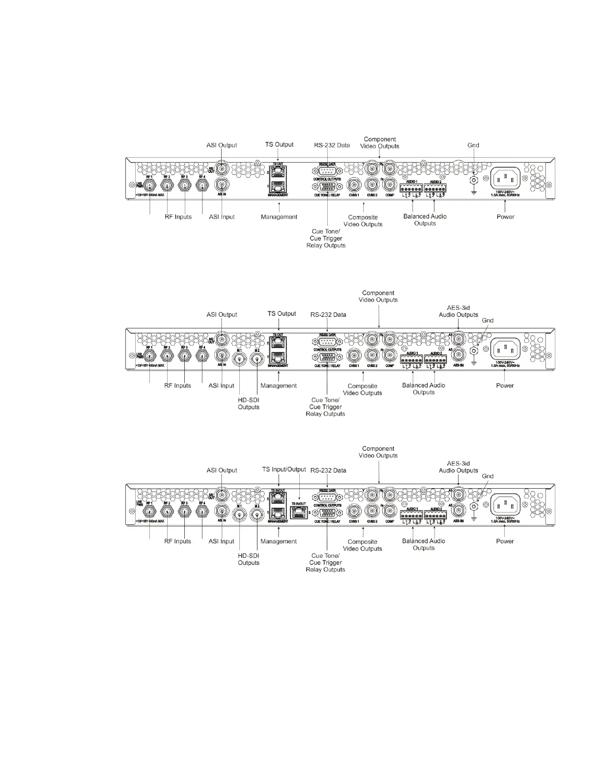
The following displays the rear panel of the D9854 Base Model:
The following displays the rear panel of the D9854 SDI Model, with SD/HD-SDI and
AES outputs:
The following displays the rear panel of the D9854-I:
1 Connect the L-Band signal to RF1. 13V or 18V LNB power is only available on
the RF1 port. The factory default setting for LNB power is OFF.
2 Connect the ASI OUT port to an ASI device for digital tier applications.
3 Connect the Composite Video Output to a video monitor.
4 Connect the terminal block balanced audio outputs labeled AUDIO 1 and
AUDIO 2 to monitoring equipment.